- 640 pages
- English
- ePUB (mobile friendly)
- Available on iOS & Android
eBook - ePub
Handbook of Mems for Wireless and Mobile Applications
About this book
The increasing demand for mobile and wireless sensing necessitates the use of highly integrated technology featuring small size, low weight, high performance and low cost: micro-electro-mechanical systems (MEMS) can meet this need. The Handbook of MEMS for wireless and mobile applications provides a comprehensive overview of radio frequency (RF) MEMS technologies and explores the use of these technologies over a wide range of application areas.Part one provides an introduction to the use of RF MEMS as an enabling technology for wireless applications. Chapters review RF MEMS technology and applications as a whole before moving on to describe specific technologies for wireless applications including passive components, phase shifters and antennas. Packaging and reliability of RF MEMS is also discussed. Chapters in part two focus on wireless techniques and applications of wireless MEMS including biomedical applications, such as implantable MEMS, intraocular pressure sensors and wireless drug delivery. Further chapters highlight the use of RF MEMS for automotive radar, the monitoring of telecommunications reliability using wireless MEMS and the use of optical MEMS displays in portable electronics.With its distinguished editor and international team of expert authors, the Handbook of MEMS for wireless and mobile applications is a technical resource for MEMS manufacturers, the electronics industry, and scientists, engineers and academics working on MEMS and wireless systems.
- Reviews the use of radio frequency (RF) MEMS as an enabling technology for wireless applications
- Discusses wireless techniques and applications of wireless MEMS, including biomedical applications
- Describes monitoring structures and the environment with wireless MEMS
Trusted by 375,005 students
Access to over 1.5 million titles for a fair monthly price.
Study more efficiently using our study tools.
Information
Part I
RF MEMS as an enabling technology for wireless applications
1
Overview of RF MEMS technology and applications
T. Purtova and H. Schumacher, Ulm University, Germany
Abstract:
This chapter presents an introduction to radio frequency microelectromechanical systems (RF MEMS) technologies for wireless applications. It starts with reviewing the operation principle and common realizations of electrostatically actuated components. It is shown that RF MEMS advantages materialize especially at higher frequencies, and for applications requiring high linearity. The chapter then moves on to present exemplary RF MEMS applications. It is pointed out that while RF MEMS components have few opportunities as a one-on-one replacement for existing switch technologies, they are extremely attractive in RF MEMS-only subsystems. Besides, emerging monolithic BiCMOS-RF MEMS integration opens up new opportunities for millimeter-wave integrated circuits (ICs).
Key words
RF MEMS
millimetre-wave
switch
low-noise amplifier (LNA)
voltage-controlled oscillator (VCO)
impedance tuner
1.1 Introduction
Switches and variable capacitors are important building blocks of radio frequency integrated circuits (RFICs). Due to the rapid advancement of RF complementary metal–oxide–semiconductor (CMOS) technologies, MOS switches are gaining in importance, but are still used typically below 6 GHz, and rarely up to 20 GHz (e.g. Talwalkar et al., 2004; Pao et al., 2006; Jin and Nguyen, 2007). For millimetre-wave applications III-V field effect transistors (FETs) or pin-diode switches can be used (e.g. Buber et al., 2003; Kallfass et al., 2008), but they suffer from increasing losses at high frequencies. Similar arguments apply to semiconductor varactors. Besides, the linearity of all semiconductor components is rather limited.
In contrast, radio frequency microelectromechanical systems (RF MEMS) can provide low loss even at elevated frequencies and inherently high linearity, since RF MEMS components do not contain non-linear elements, such as semiconductor junctions or ferroelectrics. The low loss originates mainly from the fact that RF MEMS can be fabricated at low temperatures and thus are often made of low-loss metals, such as gold, aluminium or copper. The insertion loss of a single-pole–single-throw switch can be as low as 0.3 dB up to 100 GHz, with the upper RF power limit of 15 dBm (hot switching) (Kaynak et al., 2011, 2012). With proper techniques, RF MEMS components with several watts power handling have also been developed (e.g. Palego et al., 2010).
The purpose of this chapter is to explain concisely the operational principles of the most common RF MEMS components, their electromagnetic and electromechanical modelling, and their fabrication procedure. Those aspects in which MEMS are better than their semiconductor counterparts are discussed, while associated challenges and bottle-necks are identified. Finally, several applications for which RF MEMS are significantly more advantageous than semiconductor-based components are presented.
1.2 Radio frequency microelectromechanical systems (RF MEMS) operation principle and common realizations
The main distinguishing feature of RF MEMS is that their electromagnetic properties are mechanically reconfigurable by moveable parts. It clearly differentiates them from just ‘micromachined’, or membrane-supported, components, where no moveable parts are present and the goal is to either improve quality factors of passive components (e.g. spiral inductors (Lin et al., 2005) or transmission lines (Neculoiu et al., 2001)) or to increase antenna bandwidth (Neculoiu et al., 2004). The movement can be utilized for design of microelectromechanical switches with either capacitive or ohmic contacts. Besides, tuneable or switchable capacitors and, to a lesser extent, switchable inductors can be developed.
The moving force can be of electrostatic, thermal, electromagnetic or piezoelectric origin (a detailed description can be found, for example, in Pelesko and Bernstein (2003)). Electrostatic actuation is by far the most commonly used, due to its negligible DC power consumption, fast switching (as compared to other MEMS actuation mechanisms, for example thermal), the possibility of biasing with high-resistivity lines not interfering with the RF signal, as well as a fabrication process compatible with standard microelectronics techniques. Due to the practical importance of electrostatic actuation, its electromechanical and electromagnetic aspects are briefly reviewed below.
1.2.1 Electromechanical analysis of electrostatic MEMS
Despite the large number of possible RF MEMS realizations, all of them can be generally described by an equivalent mass-spring model (Pelesko and Bernstein, 2003). Figure 1.1 shows such a model for the electrostatic case (Purtova, 2012). It consists of a pair of plates: one suspended in the air by a spring, and one fixed to a surface. Due to an applied potential difference, V, charges of opposite polarity arise on the two plates, generating an attractive electrostatic force, which moves the suspended plate towards the fixed plate. The model has one degree of freedom, allowing movement only along the x -axis. For simplicity, but without loss of physical insight, the following analysis neglects fringing electric fields and bending of the moveable plate, resulting in an ideal parallel-plate movement (Pelesko and Bernstein, 2003).
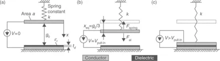
1.1 Parallel-plate model of an electrostatically actuated RF MEMS: (a) initial position, (b) at static pull-in, (c) after static pull-in. In practice, the spring displacement is much smaller than the not-toscale figure shows.
Static pull-in
Static analysis assumes that the applied voltage is increasing slowly enough that at any moment of time the system is in static equilibrium, that is, the total force is zero and the moveable plate is at rest. Thus, inertia and damping have no effect on the movement of the membrane. This somewhat artificial approach facilitates understanding of important physical processes, as shown in the following.
Initially, the two plates are at the same DC-potential (Fig. 1.1a, V = 0) and the spring is in equilibrium. As a small potential difference V is applied (Fig. 1.1b), an attractive electrostatic force Fel is created between the plates and the suspended plate moves towards the fixed plate. Simultaneously, the spring force Fspring increases to oppose this movement. For most RF MEMS, the displacement is small (typically below 1% of the spring’s length), so that the spring remains linear and the spring force Fspring is defined by Hooke’s law (Equation [1.1]):

The conductive plates in Fig. 1.1 have an area a, are separated from each other by a distance g0, the dielectric thickness is td and the suspending spring has a spring constant k and the electrostatic force Fel is given by Equation [1.2]:

For small V both forces balance each other at equilibrium position g0−xeq, obtained by equating force magnitudes: |Fel| = |Fspring|. However, above a certain v...
Table of contents
- Cover image
- Title page
- Table of Contents
- Copyright
- Contributor contact details
- Woodhead Publishing Series in Electronic and Optical Materials
- Dedication
- Preface
- Part I: RF MEMS as an enabling technology for wireless applications
- Part II: Wireless techniques and applications of wireless MEMS
- Index
Frequently asked questions
Yes, you can cancel anytime from the Subscription tab in your account settings on the Perlego website. Your subscription will stay active until the end of your current billing period. Learn how to cancel your subscription
No, books cannot be downloaded as external files, such as PDFs, for use outside of Perlego. However, you can download books within the Perlego app for offline reading on mobile or tablet. Learn how to download books offline
Perlego offers two plans: Essential and Complete
- Essential is ideal for learners and professionals who enjoy exploring a wide range of subjects. Access the Essential Library with 800,000+ trusted titles and best-sellers across business, personal growth, and the humanities. Includes unlimited reading time and Standard Read Aloud voice.
- Complete: Perfect for advanced learners and researchers needing full, unrestricted access. Unlock 1.5M+ books across hundreds of subjects, including academic and specialized titles. The Complete Plan also includes advanced features like Premium Read Aloud and Research Assistant.
We are an online textbook subscription service, where you can get access to an entire online library for less than the price of a single book per month. With over 1.5 million books across 990+ topics, we’ve got you covered! Learn about our mission
Look out for the read-aloud symbol on your next book to see if you can listen to it. The read-aloud tool reads text aloud for you, highlighting the text as it is being read. You can pause it, speed it up and slow it down. Learn more about Read Aloud
Yes! You can use the Perlego app on both iOS and Android devices to read anytime, anywhere — even offline. Perfect for commutes or when you’re on the go.
Please note we cannot support devices running on iOS 13 and Android 7 or earlier. Learn more about using the app
Please note we cannot support devices running on iOS 13 and Android 7 or earlier. Learn more about using the app
Yes, you can access Handbook of Mems for Wireless and Mobile Applications by Deepak Uttamchandani in PDF and/or ePUB format, as well as other popular books in Technology & Engineering & Electrical Engineering & Telecommunications. We have over 1.5 million books available in our catalogue for you to explore.