
eBook - ePub
Industrial Electronics for Engineers, Chemists, and Technicians
With Optional Lab Experiments
- 317 pages
- English
- ePUB (mobile friendly)
- Available on iOS & Android
eBook - ePub
Industrial Electronics for Engineers, Chemists, and Technicians
With Optional Lab Experiments
About this book
Turn to this multipurpose reference for a practical understanding of electronics in the factory or laboratory. It's perfect for people who are not electrical engineers but who need to use electronic equipment every day at work. Avoid or solve common problems in the use of electronics in the factory or lab and optimize the use of measurement and control equipment with this helpful resource!The guide is easy to understand by anyone who has taken a high school physics courseùyet it provides quick, specific solutions for such electronics issues as feedback oscillation, ground loops, impedance mismatch, noise pickup, and optimization of PID controllers.Use Industrial Electronics as a hands-on resource to handle typical electronics questions as they arise, as a self-study text to provide a broad background for understanding general electronics issues and design, or even for an instructor-led, on-the-job training course in shop or lab electronics. Because of the highly detailed explanations in the book, instructors themselves do not need to be experts. Of course, the volume is perfect for use as a textbook in college and vocational school courses.The laboratory experiments are optional and may be used merely as examples. Components are inexpensive and can be obtained from consumer electronics stores such as Radio Shack or from electronics suppliers on the Web. The circuit diagrams are greatly simplified and completely understandable, with every component explained.
Trusted by 375,005 students
Access to over 1.5 million titles for a fair monthly price.
Study more efficiently using our study tools.
Information
CHAPTER 1
Introduction
Instead of an introductory chapter that presents a mass of text about the history of electronics, or its importance in modern life, this chapter will start right in with experiments illustrating the “inductive kick” that sometimes destroys expensive computers. These experiments also include making a simple radio transmitter of the type that saved 600 people on the ship Titanic.
THE INDUCTIVE, DESTRUCTIVE KICK
When electricity flows through a coil of wire, the physical phenomenon of “inductance” becomes strong enough to be easily detected. This is similar to a heavy iron piston moving through a water pipe, along with the water. It is difficult to get it to start moving, but once it moves, the heavy piston is hard to stop. Of course, with the heavy mass of iron, the phenomenon is commonly called inertia. This can be considered to be an “analog” of inductance, which means that, although inertia and inductance are not really the same, they behave similarly in some ways. Electricity moving through a coil (in other words, through an “inductor”) is hard to start, but it is also hard to stop after it has started flowing. In fact, it is so hard to stop, that it can cause a lot of trouble if you try to stop it too quickly.
A better understanding of inductance and other features of wire coils will be provided by later chapters in this book. However, in this chapter just the behavior itself will be studied, without analyzing why it behaves this way.
EXPERIMENTS
Before beginning the experiments, a few procedural things have to be covered. The source of electricity will be a 9 volt battery, and the connections will be made through clip leads. (The latter word is pronounced “leed,” not “led” like lead metal would be.) In supply catalogs, the clip leads are sometimes described by other phrases such as “test leads,” “jumper cables,” or “patch cords.” Because of their appearance, the adjustable connectors at the ends are called “alligator clips.”
By squeezing the large end of the alligator clip, along with its soft plastic insulator, the small end of the clip will open, and that is then placed on the rim of one circular metal terminal of the battery, and the opening force is then released. While this is quite obvious (almost insultingly so), what is not obvious to many students is that the two metal clips (positive and negative) must be carefully prevented from touching the outer metal casing of the battery, or touching each other. This can best be done by arranging the two clips as symbolized by the black rectangles in Fig. 1.1, although the wires are actually coming out of the page toward you, and not going upwards as shown in the figure. Black wires are usually put on the negative terminal and red on the positive one.
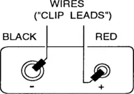
Figure 1.1 Special arrangement for attaching clips to a 9V battery.
If the plastic covering slips off an alligator clip, which does often happen, open the clip as before, and then put your other hand “in the alligator’s mouth,” which can be done without hurting your fingers by squeezing the imaginary “animal’s cheeks” sideways into its “mouth.” Holding the clip open in that manner, your first hand can easily slip the plastic back over the large end of the clip. (Students who did not know this trick have been observed by the author to be angrily wrestling with those slippery plastic insulators, eventually giving up, and then letting the clips remain uninsulated.)
Following the circuit diagram of Fig. 1.2, run the battery current through the 120V/12V transformer, using only the “secondary” side. The way to interpret Fig. 1.2 (hopefully not being too obvious) is to attach one end of a black clip lead to the bottom end of the battery as shown in the figure. This is the negative terminal, which is the larger (“female”) metal circle on the end of the actual battery, as shown previously in Fig. 1.1.
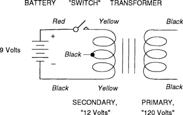
Figure 1.2 Generating a pulse by stopping the current in an inductor.
Connect the other end of that same clip lead to either one of the two secondary wires on the transformer, which both have thin yellow plastic insulation on them. Do not use any of the black wires of this transformer, either the thinly insulated “center tap” of the secondary coil or the two thickly insulated black wires of the “primary” coil. (This experiment can be done either with or without a long “power cord” and plug attached to the primary.)
The reader probably knows from high school science courses that the primary coil of this transformer usually has several hundred “turns” of wire in its coil, although the transformer symbol used in this book only shows 3 turns. The secondary would have only one tenth as many turns, but for simplicity, each of the “windings” is shown here as having 3 turns. In this experiment the windings are not being used as a transformer — we are merely using one part as a simple inductor.
Negative wires are often considered to be “grounds,” even though this one is not actually connected to the true ground. It is usually best to be consistent and have black or green colored wires be the negative ground connections, in order to avoid mistakes. It is also best to make all the ground connections first, because in case mistakes are made later (which often happens when the circuits get more complicated), it is easier to trace errors if the grounds are all completed before attaching the positive wires. The negative ground connections are arbitrarily defined to be at zero voltage, so the positive wires can be considered as being +9 volts “above the ground potential.”
At the upper end of the secondary coil, the symbol that is labeled “switch” in the diagram represents a contact that is made and then broken, repeatedly. It could be a real switch, such as you would use to turn on the lights in a classroom, but to save money we will just use one end of a clip lead that is touched for a short time to the upper transformer secondary wire.
SAFETY NOTE: Do not touch wires with more than one hand at a time while generating an inductive kick in the next part of this experiment. The high voltage can go through the thin plastic insulation and give you a slight shock if two hands are used. Although these voltages are high, the currents are very small, so such a shock would not be dangerous to most people, and in fact most people would not even be able to feel it. However, some people can feel it, and a person with a weak heart could have a temporary arrhythmia attack with even a slight electric shock.
Now connect a clip lead (preferably red) to the positive (“male”) battery terminal. Using only one hand, touch the other end of that clip lead to the other secondary transformer wire for only about one second (enough time for the electric current to build up in the rather sluggish inductor), but after that short time, disconnect it again with a quick motion. (That will be equivalent to having a switch in the circuit and turning it on and then off, but as mentioned above, an actual switch will not be used.) A small spark will appear when you disconnect the wire, because the electricity has a strong tendency to continue flowing — the inductance of the coil causes it to behave this way. Instead of suddenly stopping, the electricity builds up enough voltage (in other words, enough driving force) to continue flowing in the visible form of a spark, going right through the air. But as your hand quickly moves the alligator clip farther away from the transformer wire, the distance soon gets to be too great for the available voltage to continue pushing the electricity, so it stops. Thus the spark only lasts for about a thousandth of a second.
There was no spark when you made initial contact, only when you broke the contact. However, you might have caused the two pieces of metal to “bounce” (make and then break contact very fast) before settling down, while you were trying to push them together. In that case there would be a visible spark when you “made contact,” because you were really making and then breaking it, and the breaking action was where the spark actually occurred. This is referred to in electronics as “contact bounce,” and although we try to avoid it, various switches, push buttons, and computer keyboards do sometimes have contact bounce, and it can cause errors in computerized data. Circuits for preventing the effects of this will be discussed in later chapters.
If the sparking is repeated many times, the battery will be temporarily drained, and the spark might stop appearing. In that case, wait a minute for the battery to recover its proper voltage and then try again.
This spark is not very impressive. However, the little spark represents a very high voltage, even if it only exists for a small time. In fact, if you tried to use a voltmeter or oscilloscope to measure this high voltage, it might destroy those instruments. Instead, we will use a “neon tester bulb” to get an estimate of the voltage, where even an extremely high voltage will not damage it.
On the wall of your classroom, find a 120 volt electric socket. Into the two rectangular holes of that socket, plug in the two wires of the neon tester, being very careful not to let your hand slip forward and touch the metal “lugs” at the ends of the wires. Exert your will power to use only one hand for this operation, resisting the urge to make things easier by putting both hands on the wires. (If you happen to slip, the shock of having the 120 volts go from one finger to another, all on the same hand, would not be as likely to kill you as having it go from one hand to the other, across your heart area. Therefore, get in the habit of only using one hand when working with any source of more than 50 volts. This is the electrician’s “keep the other hand in your pocket” safety rule.) If you are not in the United States of America, possibly you will need to plug into differently shaped holes (round or L-shaped), and you might have a different voltage, but the experiment will be similar.
Some instructors may insist that students wear rubber or cloth gloves during this part of the experiment, or possibly the instructor will be the only person allowed to do it. In case someone is apparently becoming paralyzed by accidental contact to the high voltage source, do not help that person by grabbing the body with your bare hands, because you might also become shocked and temporarily paralyzed. Instead, either use a gloved hand or else push the person away from the wall socket with your foot, only making contact with a rubber soled shoe. Although kicking your friend when he is paralyzed sounds humorous, of course an electric shock is not funny when it occu...
Table of contents
- Cover image
- Title page
- Table of Contents
- Copyright
- PREFACE
- Chapter 1: Introduction
- Chapter 2: Ohm’s Law and Measurements
- Chapter 3: Resistances in Parallel
- Chapter 4: Series Resistances, Part I: Bad Output Voltages
- Chapter 5: Series Resistances, Part II: Bad Measurements
- Chapter 6: Series Resistances, Part III: Bad Grounds
- Chapter 7: Soldering
- Chapter 8: The Oscilloscope
- Chapter 9: Capacitors
- Chapter 10: Inductors
- Chapter 11: Filters and Resonance
- Chapter 12: Relays
- Chapter 13: Semiconductors
- Chapter 14: Diodes
- Chapter 15: The Bipolar Transistor
- Chapter 16: Sine Wave Oscillators
- Chapter 17: Multivibrators
- Chapter 18: FETs and Tubes
- Chapter 19: Radio and Modulation
- Chapter 20: Electric Motors
- Chapter 21: SCRs and Triacs
- Chapter 22: Photonics
- Chapter 23: Analog Op-Amp ICs
- Chapter 24: Digital Microprocessor ICs
- Equipment List for Entire Course
- APPENDIX
- GLOSSARY
- INDEX
Frequently asked questions
Yes, you can cancel anytime from the Subscription tab in your account settings on the Perlego website. Your subscription will stay active until the end of your current billing period. Learn how to cancel your subscription
No, books cannot be downloaded as external files, such as PDFs, for use outside of Perlego. However, you can download books within the Perlego app for offline reading on mobile or tablet. Learn how to download books offline
Perlego offers two plans: Essential and Complete
- Essential is ideal for learners and professionals who enjoy exploring a wide range of subjects. Access the Essential Library with 800,000+ trusted titles and best-sellers across business, personal growth, and the humanities. Includes unlimited reading time and Standard Read Aloud voice.
- Complete: Perfect for advanced learners and researchers needing full, unrestricted access. Unlock 1.5M+ books across hundreds of subjects, including academic and specialized titles. The Complete Plan also includes advanced features like Premium Read Aloud and Research Assistant.
We are an online textbook subscription service, where you can get access to an entire online library for less than the price of a single book per month. With over 1.5 million books across 990+ topics, we’ve got you covered! Learn about our mission
Look out for the read-aloud symbol on your next book to see if you can listen to it. The read-aloud tool reads text aloud for you, highlighting the text as it is being read. You can pause it, speed it up and slow it down. Learn more about Read Aloud
Yes! You can use the Perlego app on both iOS and Android devices to read anytime, anywhere — even offline. Perfect for commutes or when you’re on the go.
Please note we cannot support devices running on iOS 13 and Android 7 or earlier. Learn more about using the app
Please note we cannot support devices running on iOS 13 and Android 7 or earlier. Learn more about using the app
Yes, you can access Industrial Electronics for Engineers, Chemists, and Technicians by Daniel J. Shanefield in PDF and/or ePUB format, as well as other popular books in Technology & Engineering & Electrical Engineering & Telecommunications. We have over 1.5 million books available in our catalogue for you to explore.