
eBook - ePub
The Effect of Creep and Other Time Related Factors on Plastics and Elastomers
- 432 pages
- English
- ePUB (mobile friendly)
- Available on iOS & Android
eBook - ePub
The Effect of Creep and Other Time Related Factors on Plastics and Elastomers
About this book
The second edition of the classic data book, The Effect of Creep and Other Time Related Factors on Plastics and Elastomers (originally published in 1991), has been extensively revised with the addition of an abundance of new data, the removal of all out-dated information, and the complete rebuilding of the product and company listings.This new edition also has been reorganized from a polymer chemistry point of view. Plastics of similar polymer types are grouped into chapters, each with an introduction that briefly explains the chemistry of the polymers used in the plastics. An extensive introductory chapter has also been added, which summarizes the chemistry of making polymers, the formulation of plastics, creep-testing, test methods, measurements, and charts, as well as theory and plastic selection.Each chapter is generally organized by product and concludes with comparisons of brand or generic products. The appendices include a list of trade names, plastics sold under those names, and manufacturer. A list of conversion factors for stress measures is also included.ABOUT THE AUTHORLaurence W. McKeen earned a B.S. in Chemistry from Rensselaer Polytechnic Institute in 1973 and a Ph.D. in 1978 from the University of Wisconsin. He began his career with DuPont in 1978 as a mass spectroscopist, but moved into product development in the Teflon® Finishes group in 1980. Dr. McKeen has accumulated over 28 years of experience in product development and applications, working with customers in a wide range of industries, which has led to the creation of dozens of commercial products.
- More than 8 core chapters, which serve as a databank for evaluating the creep of plastics
- Over 600 uniform graphs for more than 45 generic families of plastics are explained
- Types of graphs include: (1) Isochronous Stress–Strain Curves at Various Times and Temperatures (2) Creep Strain or Creep Deformation versus Time at Various Stress Levels and Temperatures (3) Various Modulus Measures (Tensile, Compressive, Flexural) versus Time at Various Temperatures (4) Hoop Stress versus Time at Various Temperatures (5) Stress Cracking and Other Plastics Failure versus Time (6) Creep Rupture versus Time
Trusted by 375,005 students
Access to over 1.5 million titles for a fair monthly price.
Study more efficiently using our study tools.
Information
Chapter 1
Introduction to Plastics and Elastomers
1.1 Introduction
In an earlier book in this series, The Effect of Temperature and Other Factors on Plastics and Elastomers,1 the general mechanical properties of plastics were discussed. These mechanical properties as a function of temperature, humidity, and other factors are presented in graphs or tables. That work includes hundreds of graphs of stress versus strain, modulus versus temperature, impact strength versus temperature, etc. However, when one starts designing products made of plastics, these graphs do not supply all the necessary information. This is because these graphs show the results of relatively short-term tests. Their value in design is in the initial selection of materials in terms of stiffness, strength, etc. Designs based on short-term data obtained from a short-term test would not predict accurately the long-term behavior of plastics. This is partly because plastics are viscoelastic materials. Viscoelastic by definition means possessing properties that are both solid-like and liquid-like. More precisely with reference to plastics, viscoelastic means that measurements such as modulus, impact strength, and coefficient of friction are sensitive not only to straining rate, temperature, humidity, etc., but also to elapsed time and loading history. The manufacturing method used for the plastic product can also create changes in the structure of the material, which have a pronounced effect on properties.
The rest of this chapter first deals with the types of stress and provides a short introduction to creep. Then the chemistry of plastics is discussed and because plastics are polymeric materials the focus is more on polymer chemistry. The discussion includes polymerization chemistry and the different types of polymers and how they differ from each other. As plastics are rarely “neat,” reinforcements, fillers, and additives are reviewed. This is followed by a detailed look at creep, including creep-specific tests and creep graphs. The discussion takes a look at what happens at the microscopic level when plastics exhibit creep. Section 1.4. is taken from The Effect of Temperature and Other Factors on Plastics and Elastomers book, but it has been refocused on creep properties.
1.2 Types of Stress
Creep is the time-dependent change in the dimensions of a plastic article when it is subjected to a constant stress. Stress can be applied in a number of ways. Normal stress (σ) is the ratio of the applied force (F) over the cross-sectional area (A), as shown in Equation 1.1:

1.2.1 Tensile and Compressive Stress
When the applied force is directed away from the part, as shown in Fig. 1.1, it is a tensile force inducing a tensile stress. When the force is applied towards the part, it is a compressive force inducing a compressive stress.
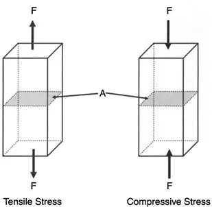
Figure 1.1. Illustration of tensile stress and compressive stress.
1.2.2 Shear Stress
Shear stress (τ) is also expressed as the force per unit area, as shown in Equation 1.2. The shear force is applied parallel to the cross-sectional area “A” as shown in Fig. 1.2.
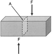
Figure 1.2. Illustration of shear stress.

1.2.3 Torsional Stress
Torsional stress (τ) occurs when a part such as a rod or shaft is twisted as in Fig. 1.3. This is also a shear stress, but the stress is variable and depends on how far the point of interest is from the center of the shaft. The equation describing this stress is shown in Equation 1.3:
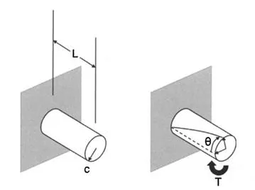
Figure 1.3. Illustration of torsional stress.

In this equation, T is the torque and c is the distance from the center of the shaft or rod. K is a torsional constant that depends on the geometry of the shaft, rod, or beam. The torque (T) is further defined by Equation 1.4, in which θ is the angle of twist, G is the modulus of rigidity (material dependent), and L is the length.

The torsional constant (K) is dependent upon geometry, and the formulas for several geometries are shown in Fig. 1.4. Additional formulas for the torsional constant have been published.2
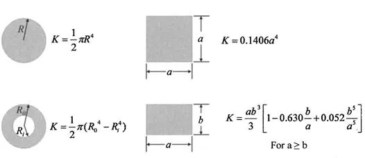
Figure 1.4. Torsional constants for rods or beams of common geometries.
1.2.4 Flexural or Bending Stress
Bending stress or flexural stress commonly occurs in two instances, as shown in Fig. 1.5. One is called a simple, supported structural beam bending and the other is called cantilever beam bending. For the simple, supported structural beam, the upper surface of the bending beam is in compression and the bottom surface is in tension. The neutral axis (NA) is a region of zero stress. The bending stress (σ) is defined by Equation 1.5, where M is the bending moment (which is calculated by multiplying a force by the distance between the point of interest and the force), c is the distance from the neutral axis (NA in Fig. 1.5), and I is the moment of inertia. The cantilevered beam configuration, which is also shown in Fig. 1.5, has a similar formula. The formulas for M, c, and I can be complex, depending on the exact configuration and beam shape, but many have been published.3
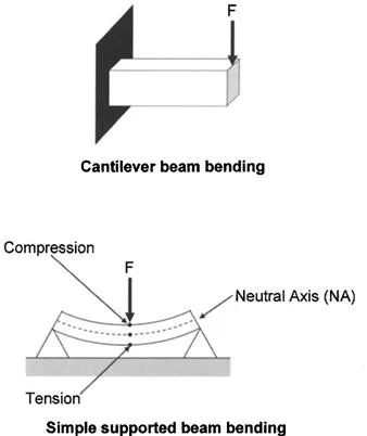
Figure 1.5. Illustration of flexural or bending stress.

1.2.5 Hoop Stress
Hoop stress (σh) is the mechanical stress defined for rotationally symmetric objects such as pipe or tubing. The real world view of hoop stress is the tension applied to the iron bands, or hoops, of a wooden barrel. It is the result of forces acting circumferentially. Figure 1.6 shows stresses caused by the pressure (P) inside a cylindrical vessel. The hoop stress is indicated on the right in Fig. 1.6, which shows a segment of the pipe.
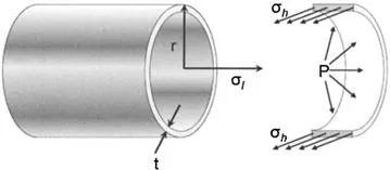
Figure 1.6. Illustration of hoop stress.
The classic equation for hoop stress created by an internal pressure on a thin-wall cylindrical pressure vessel is given in Equation 1.6:

where P is the internal pressure, t is the wall thickness, and r is the radius of the cylinder. The SI unit for P is pascal (Pa), while t and r are in meters (m).
If the pipe is closed at the ends, any force applied on them by the internal pressure will induce an axial or longitudinal stress (σ1) on the same pipe wall. The longitudinal stress, under the same conditions as in Fig. 1.6, is given by Equation 1.7:

There could also be a radial stress especially when the pipe walls are thick, but thin-walled sections often have negligibly small radial stress (σr). The stress in the radial direction at a point in the tube or cylinder wall is shown in Equation 1.8:
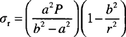
where P is the internal pressure in the tube or cylinder, a is the internal radius of the tube or cylinder, b is the external radius of the tube or cylinder, and r is the radius to the point in tube where the radial stress is calculated.
Often the stresses in a pipe are combined into a measure called the equivalent stress, which is determined using the Von Mises equivalent stress formula shown in Equation 1.9:
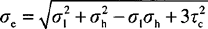
where σ1 is the longitudinal stress, σh is the hoop stress, and τc is the tangential shear stress (from material flowing through the pipe).
Failure by fracture in cylindrical vessels is dominated by hoop stress in the absence of other external loads because it is the largest principal stress...
Table of contents
- Cover image
- Title page
- Table of Contents
- Copyright
- Preface
- Chapter 1. Introduction to Plastics and Elastomers
- Chapter 2. Styrenic Plastics
- Chapter 3. Polyether Plastics
- Chapter 4. Polyesters
- Chapter 5. Polyimides
- Chapter 6. Polyamides (Nylons)
- Chapter 7. Polyolefins and Acrylics
- Chapter 8. Thermoplastic Elastomers
- Chapter 9. Fluoropolymers
- Chapter 10. High-Temperature Polymers
- Chapter 11. Table of Poisson’s Ratios
- APPENDIX 1: Abbreviations
- APPENDIX 2: List of Trade Names
- APPENDIX 3: Unit Conversion Tables
- Index
Frequently asked questions
Yes, you can cancel anytime from the Subscription tab in your account settings on the Perlego website. Your subscription will stay active until the end of your current billing period. Learn how to cancel your subscription
No, books cannot be downloaded as external files, such as PDFs, for use outside of Perlego. However, you can download books within the Perlego app for offline reading on mobile or tablet. Learn how to download books offline
Perlego offers two plans: Essential and Complete
- Essential is ideal for learners and professionals who enjoy exploring a wide range of subjects. Access the Essential Library with 800,000+ trusted titles and best-sellers across business, personal growth, and the humanities. Includes unlimited reading time and Standard Read Aloud voice.
- Complete: Perfect for advanced learners and researchers needing full, unrestricted access. Unlock 1.5M+ books across hundreds of subjects, including academic and specialized titles. The Complete Plan also includes advanced features like Premium Read Aloud and Research Assistant.
We are an online textbook subscription service, where you can get access to an entire online library for less than the price of a single book per month. With over 1.5 million books across 990+ topics, we’ve got you covered! Learn about our mission
Look out for the read-aloud symbol on your next book to see if you can listen to it. The read-aloud tool reads text aloud for you, highlighting the text as it is being read. You can pause it, speed it up and slow it down. Learn more about Read Aloud
Yes! You can use the Perlego app on both iOS and Android devices to read anytime, anywhere — even offline. Perfect for commutes or when you’re on the go.
Please note we cannot support devices running on iOS 13 and Android 7 or earlier. Learn more about using the app
Please note we cannot support devices running on iOS 13 and Android 7 or earlier. Learn more about using the app
Yes, you can access The Effect of Creep and Other Time Related Factors on Plastics and Elastomers by Laurence W. McKeen in PDF and/or ePUB format, as well as other popular books in Technology & Engineering & Industrial Design. We have over 1.5 million books available in our catalogue for you to explore.