eBook - ePub
Control in Power Electronics
Selected Problems
- 544 pages
- English
- ePUB (mobile friendly)
- Available on iOS & Android
eBook - ePub
Control in Power Electronics
Selected Problems
About this book
The authors were originally brought together to share research and applications through the international Danfoss Professor Programme at Aalborg University in Denmark.
Personal computers would be unwieldy and inefficient without power electronic dc supplies. Portable communication devices and computers would also be impractical. High-performance lighting systems, motor controls, and a wide range of industrial controls depend on power electronics. In the near future we can expect strong growth in automotive applications, dc power supplies for communication systems, portable applications, and high-end converters. We are approaching a time when all electrical energy will be processed and controlled through power electronics somewhere in the path from generation to end use.
- The most up-to-date information available is presented in the text
- Written by a world renowned leader in the field
Trusted by 375,005 students
Access to over 1.5 million titles for a fair monthly price.
Study more efficiently using our study tools.
Information
Part I
PWM Converters: Topologies and Control
CHAPTER 1
Power Electronic Converters
ANDRZEJ M. TRZYNADLOWSKI, University of Nevada, Reno, Nevada
This introductory chapter provides a background to the subject of the book. Fundamental principles of electric power conditioning are explained using a hypothetical generic power converter. Ac to dc, ac to ac, dc to dc, and dc to ac power electronic converters are described, including select operating characteristics and equations of their most common representatives.
1.1 PRINCIPLES OF ELECTRIC POWER CONDITIONING
Electric power is supplied in a “raw,” fixed-frqency, fixed-voltage form. For small consumers, such as homes or small stores, usually only the single-phase ac voltage is available, whereas large energy users, typically industrial facilities, draw most of their electrical energy via three-phase lines. The demand for conditioned power is growing rapidly, mostly because of the progressing sophistication and automation of industrial processes. Power conditioning involves both power conversion, ac to dc or dc to ac, and control. Power electronic converters performing the conditioning are highly efficient and reliable.
Power electronic converters can be thought of as networks of semiconductor power switches. Depending on the type, the switches can be uncontrolled, semicontrolled, or fully controlled. The state of uncontrolled switches, the power diodes, depends on the operating conditions only. A diode turns on (closes) when positively biased and it turns off (opens) when the conducted current changes its polarity to negative. Semicontrolled switches, the SCRs (silicon controlled rectifiers), can be turned on by a gate current signal, but they turn off just like the diodes. Most of the existing power switches are fully controlled, that is, they can both be turned on and off by appropriate voltage or current signals.
Principles of electric power conversion can easily be explained using a hypothetical “generic power converter” shown in Fig. 1.1. It is a simple network of five switches, S0 through S4, of which S1 opens and closes simultaneously with S2, and S3 opens and closes simultaneously with S4. These four switches can all be open (OFF), but they may not be all closed (ON) because they would short the supply source. Switch S0 is only closed when all the other switches are open. It is assumed that the switches open and close instantly, so that currents flowing through them can be redirected without interruption.
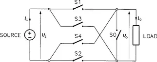
FIGURE 1.1 Generic power converter.
The generic converter can assume three states only: (1) State 0, with switches S1 through S4 open and switch S0 closed, (2) State 1, with switches S1 and S2 closed and the other three switches open, and (3) State 2, with switches S3 and S4 closed and the other three switches open. Relations between the output voltage, vo, and the input voltage, vi, and between the input current, ii, and output current, i0, are

and

Thus, depending on the state of generic converter, its switches connect, cross-connect, or disconnect the output terminals from the input terminals. In the last case (State 0), switch SO provides a path for the output current (load current) when the load includes some inductance, L. In absence of that switch, interrupting the current would cause a dangerous impulse overvoltage, Ldio/dt → –∞.
Instead of listing the input–output relations as in Eqs. (1.1) and (1.2), the so-called switching functions (or switching variables) can be assigned to individual sets of switches. Let a = 0 when switch SO is open and a = 1 when it is closed, b = 0 when switches S1 and S2 are open and b = 1 when they are closed, and c = 0 when switches S3 and S4 are open and c = 1 when they are closed. Then,

and

The ac to dc power conversion in the generic converter is performed by setting it to State 2 whenever the input voltage is negative. Vice-versa, the dc to...
Table of contents
- Cover image
- Title page
- Table of Contents
- ACADEMIC PRESS SERIES IN ENGINEERING
- Copyright
- Preface
- List of Contributors
- Part I: PWM Converters: Topologies and Control
- Part II: Motor Control
- Part III: Utilities Interface and Wind Turbine Systems
- Index
Frequently asked questions
Yes, you can cancel anytime from the Subscription tab in your account settings on the Perlego website. Your subscription will stay active until the end of your current billing period. Learn how to cancel your subscription
No, books cannot be downloaded as external files, such as PDFs, for use outside of Perlego. However, you can download books within the Perlego app for offline reading on mobile or tablet. Learn how to download books offline
Perlego offers two plans: Essential and Complete
- Essential is ideal for learners and professionals who enjoy exploring a wide range of subjects. Access the Essential Library with 800,000+ trusted titles and best-sellers across business, personal growth, and the humanities. Includes unlimited reading time and Standard Read Aloud voice.
- Complete: Perfect for advanced learners and researchers needing full, unrestricted access. Unlock 1.5M+ books across hundreds of subjects, including academic and specialized titles. The Complete Plan also includes advanced features like Premium Read Aloud and Research Assistant.
We are an online textbook subscription service, where you can get access to an entire online library for less than the price of a single book per month. With over 1.5 million books across 990+ topics, we’ve got you covered! Learn about our mission
Look out for the read-aloud symbol on your next book to see if you can listen to it. The read-aloud tool reads text aloud for you, highlighting the text as it is being read. You can pause it, speed it up and slow it down. Learn more about Read Aloud
Yes! You can use the Perlego app on both iOS and Android devices to read anytime, anywhere — even offline. Perfect for commutes or when you’re on the go.
Please note we cannot support devices running on iOS 13 and Android 7 or earlier. Learn more about using the app
Please note we cannot support devices running on iOS 13 and Android 7 or earlier. Learn more about using the app
Yes, you can access Control in Power Electronics by Marian P. Kazmierkowski,Ramu Krishnan,Frede Blaabjerg, J. D. Irwin in PDF and/or ePUB format, as well as other popular books in Technology & Engineering & Electrical Engineering & Telecommunications. We have over 1.5 million books available in our catalogue for you to explore.