In materials science, dislocations are irregularities within the crystal structure or atomic scale of engineering materials, such as metals, semi-conductors, polymers, and composites. Discussing this specific aspect of materials science and engineering, Introduction to Dislocations is a key resource for students. The book provides students and practitioners with the fundamental principles required to understand dislocations. Comprised of 10 chapters, the text includes advanced computer modeling and very high-resolution electron microscopy to help readers better understand the structure of atoms close to the core of dislocations. It shows that atomic arrangement has a significant effect on the formation of dislocations and thereby on the properties of solids. The first two chapters of the book present an overview of dislocations. The crystal structures and the various defects and dislocations are discussed, and methods of observation and diagnosis of dislocations are covered. Chapters 3 to 5 discuss the behavior of dislocations and explain how changes in the structure and arrangement of atoms can affect the behavior of dislocations. The three chapters also discuss the mechanical properties of dislocations. The remaining chapters offer a detailed discussion of the mechanisms of dislocations and the mechanical strength of crystalline solids. The book is written for undergraduate- and graduate-level students in both materials science and mechanical engineering. Non-experts and novices working on mechanical properties, mechanisms of deformation and fracture, and properties of materials, as well as industrial and academic researchers, will find this book invaluable.
- Long-established academic reference by an expert author team, highly regarded for their contributions to the field.
- Uses minimal mathematics to present theory and applications in a detailed yet easy-to-read manner, making this an understandable introduction to a complex topic.
- Unlike the main competition, this new edition includes recent developments in the subject and up-to-date references to further reading and research sources.
Trusted by 375,005 students
Access to over 1.5 million titles for a fair monthly price.
Dislocations are an important class of defect in crystalline solids and so an elementary understanding of crystallinity is required before dislocations can be introduced. Metals and many important classes of non-metallic solids are crystalline, i.e. the constituent atoms are arranged in a pattern that repeats itself periodically in three dimensions. The actual arrangement of the atoms is described by the crystal structure. The crystal structures of most pure metals are relatively simple: the three most common are the body-centered cubic, face-centered cubic and close-packed hexagonal, and are described in section 1.2. In contrast, the structures of alloys and non-metallic compounds are often complex.
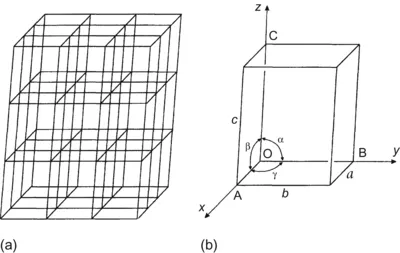
The arrangement of atoms in a crystal can be described with respect to a three-dimensional net formed by three sets of straight, parallel lines as in Fig. 1.1(a). The lines divide space into equal sized parallelepipeds and the points at the intersection of the lines define a space lattice. Every point of a space lattice has identical surroundings. Each parallelepiped is called a unit cell and the crystal is constructed by stacking identical unit cells face to face in perfect alignment in three dimensions. By placing a motif unit of one or more atoms at every lattice site the regular structure of a perfect crystal is obtained.
Figure 1.1
(a) A space lattice, (b) unit cell showing positions of principal axes.
The positions of the planes, directions and point sites in a lattice are described by reference to the unit cell and the three principal axes, x, y and z (Fig. 1.1(b)). The cell dimensions OA=a, OB=b and OC=c are the lattice parameters, and these along with the angles
,
and
completely define the size and shape of the cell. For simplicity the discussion here will be restricted to cubic and hexagonal crystal structures. In cubic crystals a=b=c and α=β=γ=90°, and the definition of planes and directions is straightforward. In hexagonal crystals it is convenient to use a different approach, and this is described in section 1.2.
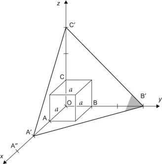
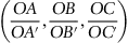
Any plane A′B′C′ in Fig. 1.2 can be defined by the intercepts OA′, OB′ and OC′ with the three principal axes. The usual notation (Miller indices) is to take the reciprocals of the ratios of the intercepts to the corresponding unit cell dimensions. Thus A′B′C′ is represented by
Figure 1.2
Cubic cell illustrating method of describing the orientation of planes.
and the numbers are then reduced to the three smallest integers in these ratios.
Thus from Fig. 1.2OA′=2a, OB′=3a, and OC′=3a, the reciprocal intercepts are
and so the Miller indices of the A′B′C′ plane are (322). Curved brackets are used for planes. A plane with intercepts OA, OB, and OC has Miller indices
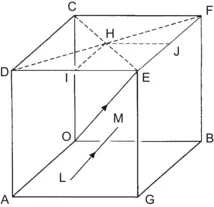
or, more simply, (111). Similarly, a plane DFBA in Fig. 1.3 is
Figure 1.3
Cubic cell illustrating the method of describing directions and point sites. LM is parallel to OE.
or (110); a plane DEGA is
or (100); and a plane AB′C′ in Fig. 1.2 is
or (311). In determining the indices of any plane it is most convenient to identify the plane of lattice points parallel to the plane which is closest to the origin O and intersects the principal axis close to the origin. Thus plane A″B′C′ in Fig. 1.2 is parallel to ABC and it is clear that the indices are (111). Using this approach it will be seen that the planes ABC, ABE, CEA and CEB in Fig. 1.3 are (111),
,
and
respectively. The minus sign above an index indicates that the plane cuts the axis on the negative side of the origin. In a cubic crystal structure, these planes constitute a group of the same crystallographic type and are described collectively by {111}.
Any direction LM in Fig. ...
Table of contents
Cover image
Table of Contents
Front-matter
Copyright
Preface
Chapter 1. Defects in Crystals
Chapter 2. Observation of Dislocations
Chapter 3. Movement of Dislocations
Chapter 4. Elastic Properties of Dislocations
Chapter 5. Dislocations in Face-centered Cubic Metals
Chapter 6. Dislocations in Other Crystal Structures
Chapter 7. Jogs and the Intersection of Dislocations
Chapter 8. Origin and Multiplication of Dislocations
Chapter 9. Dislocation Arrays and Crystal Boundaries
Chapter 10. Strength of Crystalline Solids
The SI System of Units
Index
Frequently asked questions
Yes, you can cancel anytime from the Subscription tab in your account settings on the Perlego website. Your subscription will stay active until the end of your current billing period. Learn how to cancel your subscription
No, books cannot be downloaded as external files, such as PDFs, for use outside of Perlego. However, you can download books within the Perlego app for offline reading on mobile or tablet. Learn how to download books offline
Perlego offers two plans: Essential and Complete
Essential is ideal for learners and professionals who enjoy exploring a wide range of subjects. Access the Essential Library with 800,000+ trusted titles and best-sellers across business, personal growth, and the humanities. Includes unlimited reading time and Standard Read Aloud voice.
Complete: Perfect for advanced learners and researchers needing full, unrestricted access. Unlock 1.5M+ books across hundreds of subjects, including academic and specialized titles. The Complete Plan also includes advanced features like Premium Read Aloud and Research Assistant.
Both plans are available with monthly, semester, or annual billing cycles.
We are an online textbook subscription service, where you can get access to an entire online library for less than the price of a single book per month. With over 1.5 million books across 990+ topics, we’ve got you covered! Learn about our mission
Look out for the read-aloud symbol on your next book to see if you can listen to it. The read-aloud tool reads text aloud for you, highlighting the text as it is being read. You can pause it, speed it up and slow it down. Learn more about Read Aloud
Yes! You can use the Perlego app on both iOS and Android devices to read anytime, anywhere — even offline. Perfect for commutes or when you’re on the go. Please note we cannot support devices running on iOS 13 and Android 7 or earlier. Learn more about using the app
Yes, you can access Introduction to Dislocations by Derek Hull,D. J. Bacon in PDF and/or ePUB format, as well as other popular books in Technology & Engineering & Materials Science. We have over 1.5 million books available in our catalogue for you to explore.