eBook - ePub
Radar and ARPA Manual
Radar, AIS and Target Tracking for Marine Radar Users
- 552 pages
- English
- ePUB (mobile friendly)
- Available on iOS & Android
eBook - ePub
Radar and ARPA Manual
Radar, AIS and Target Tracking for Marine Radar Users
About this book
This fully revised new edition covers the complete radar/ARPA installation and serves as the most comprehensive and up-to-date reference on equipment and techniques for radar observers using older and newer systems alike. Suitable for use as a professional reference or as a training text, the book covers all aspects of radar, ARPA and integrated bridge systems technology (including AIS, ECDIS and GNSS) and their role in shipboard operations. It is a valuable resource for larger vessels and also covers the needs of leisure and amateur sailors for whom this technology is now accessible.
Radar and ARPA Manual provides essential information for professional mariners, including those on training courses for electronic navigation systems and professional certificates internationally. Reference is made throughout to IMO (International Maritime Organization) Performance Standards, the role of radar in navigation and in collision avoidance, and to international professional and amateur marine operations qualifications.
- The most up-to-date book available, with comprehensive treatment of modern radar and ARPA systems and ECDIS (Electronic Chart Display & Information Systems)
- Full coverage of IMO performance standards relating to radar and navigational technology on new and established vessels
- Covers best practice use of equipment as well as underlying principles, with essential mathematics and complicated concepts illustrated through the use of clear illustrations
Trusted by 375,005 students
Access to over 1.5 million titles for a fair monthly price.
Study more efficiently using our study tools.
Information
Chapter 1
Basic Radar Principles
Here, basic, physical principles are discussed, how they are applied, along with the equipment used to translate theses principles, i.e. timed echo response, and rotating beam into the traditional radar picture. Next, are the ways in which the picture may be orientated i.e. Head Up Display, North Up Display and the effects of changes in course. Then there are the ways in which the picture might be stabilised using course and speed inputs. Relative Motion and, True Motion obtained using a speed input are examined along with the data obtainable from ‘plotting’ The possible misconception which might arise from a failure to plot. The importance of accuracy of any data fed to the equipment either manually or automatically. The relationship between the Head Up Display and the visual scene. The relationship between the North Up Display and the conventional navigational Chart. The effects of altering course on both types of display
Keywords
Block diagram; Head up display; North up display; Course up display; Relative Motion; True Motion; Stabilisation; Orientation; Range; Bearing; Ground stabilised; Sea Stabilized; Radar Equation; Plotting; Trails; Yaw; Plan Position Indicator (PPI); Antenna
1.1 Introduction
Radar forms an important component of the navigational equipment fitted on virtually all vessels apart from the very smallest. Its display of critical information is easily assimilated by a trained user and has acted as a focus for the presentation of other navigational data, giving it a deserved prominence on the bridge of a vessel. It is poised to retain its central electronic navigational role into the foreseeable future, equalled only in display significance by the rather more recent development, the electronic chart. Together, they will provide the basis of the major displays for marine navigation into an increasingly integrated navigational world.
The word RADAR is an acronym derived from the words Radio Detection and Ranging. The scientist Heinrich Hertz, after whom the basic unit of frequency is named, demonstrated in 1886 that radio waves could be reflected from metallic objects. In 1904 a German engineer, Christian Hülsmeyer, obtained a patent in several countries for a radio wave device capable of detecting ships, but it aroused little enthusiasm because of its very limited range. Marconi, delivering a lecture in 1922, drew attention to the work of Hertz and proposed in principle what we know today as marine radar. Although radar was used to determine the height of the ionosphere in the mid-1920s, it was not until 1935 that radar pulses were successfully used to detect and measure the range of an aircraft. In the 1930s there was much simultaneous but independent development of radar techniques in Britain, Germany, France and America. Radar first went to sea in a warship in 1937 and by 1939 considerable improvement in performance had been achieved. By 1944 naval radar had made an appearance on merchant ships and from about the end of the Second World War the growth of civil marine radar began. Progressively it was refined to meet the needs of peacetime navigation and collision avoidance.
The civil marine radars in use today differ markedly from their ancestors of the 1940s in size, appearance and versatility, but the basic data that they offer, namely target range and bearing, are determined by exploiting the same fundamental principles unveiled so long ago. An understanding of such principles is an essential starting point in any study of marine radar, even though recent developments in the use of a technology known as coherent radar have somewhat complicated the picture. This latter technology is explained in some detail in Section 2.9, but first it is useful to gain an understanding of the basic principles behind radar.
1.2 Principles of Range and Bearing Measurement
1.2.1 The Echo Principle
An object (normally referred to as a target) is detected by the transmission of radio energy as a pulse or otherwise, and the subsequent reception of a fraction of such energy (the echo) which is reflected by the target in the direction of the transmitter. The phenomenon is analogous to the reflection of sound waves from land formations and large buildings. Imagine somebody giving a short sharp shout through cupped hands to focus the sound energy. The sound wave travels outwards and some of it may strike, for example, a cliff. Some of the energy which is intercepted will be reflected by the cliff. If the reflected energy returns in the direction of the caller, and is of sufficient strength, it will be heard as an audible echo, resembling the original shout. In considering this analogy, the following points can usefully assist in gaining a preliminary understanding of pulse radar detection:
A. The echo is never as loud as the original shout.
B. The chance of detecting an echo depends on the loudness and duration of the shout.
C. Short shouts are required if echoes from close targets are not to be drowned by the original shout.
D. A sufficiently long interval between shouts is required to allow time for echoes from distant targets to return.
E. It can be more effective to cup one’s hands over the mouth when shouting and put a hand to the ear when listening for the echo.
Now considering radar, its basic building blocks are illustrated diagrammatically in Figure 1.1. The antenna is used both to transmit the signal and to receive its reflection. On transmit, the antenna is acting very much like the cupped hand, focussing the energy in a particular direction. On receive it is acting more like a hand to the ear, collecting more received energy from that direction. The transmitter has a similar role to that of the mouth and vocal chords of the shouter, and the radar receiver acts as the ear. The processor clarifies the received signal and judges its distance, perhaps somewhat similar to what a trained human brain can do in identifying and assessing a received sound wave. Finally the radar displays the information to a human operator, perhaps analogous to a human writing down the estimated range and direction of the object producing the echo.
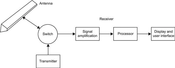
Figure 1.1 The basic radar system.
The antenna of a marine radar rotates steadily in the horizontal plane giving a complete rotation about every 2 s. This means that radar pulses consecutively cover all directions over 360° at each rotation of the antenna. The speed of radio waves is so high, about one million times greater than sound waves, that the antenna receives all the reflected energy from a particular transmitted pulse before it has appreciably rotated.
1.2.2 Range as a Function of Time
It is self-evident that the time which elapses between the transmission of a pulse and the reception of the corresponding echo depends on the speed of the pulse and the distance which it has travelled in making its two-way journey. If the speed of the pulse is known and the elapsed time can be measured, the range of the target producing the echo can be calculated.
The velocity of radio waves is dependent on the nature of the medium through which they travel. In fact, within the Earth’s atmosphere it is hardly different to that within a space-type vacuum, that is 299,792,458 m/s. In our own minds this is easiest to be considered to be almost precisely 300,000,000 (three hundred million) metres per second, or as 300 metres per microsecond (µs), where 1 µs represents one millionth part of a second (i.e. 10−6 s). Using this value it is possible to produce a simple general relationship between target range and the elapsed time which separates the transmission of the pulse and the reception of an echo in any particular case (Figure 1.2).
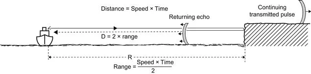
Figure 1.2 The echo principle.
Let D=the distance travelled by the pulse to and from the target (metres)
R=the range of the target (m)
T=the elapsed time (µs)
S=the speed of radio waves (m/µs)
Then D=S×T
and R=(S×T)/2
hence R=(300×T)/2
thus R=150T
The application of this relationship can be illustrated by the following example.
This result is noteworthy as it represents the elapsed time for a commonly used marine radar range scale. The elapsed times established in this section are of the order of millionths of a second and therefore need special instrumentation to be able to measure them accurately. In the early days of radar this was cutting-edge technology, but with the advent of quartz timing technology, and fast microelectronics it is no longer a major issue. Such technology is low cost, accurate and ubiquitous, with most humans owning multiple examples of precision timing in their watches, mobile phones, computers, TVs and cars.
1.2.3 Directional Transmission and Reception
In a marine radar system it is cost and space effective to use a single antenna for both transmission and reception. It is designed in such a way (see Section 2.5) as to focus the transmitted energy into a beam which is very narrow in the horizontal plane. The angle within which the energy is constrained is called the horizontal beamwidth (Figure 1.3). It must have a value of not more than 2.0° if it is to comply with the international regulations which govern marine radar. Civil marine radars for large ships are available with horizontal beamwidths as narrow as 0.75°. The equivalent reception property of the antenna is such that it will detect energy which has returned from within the angular limits of the horizontal beamwidth; that is from those targets that have been illuminated by the corresponding radar transmission. Its insensitivity to picking up unwanted noise from other directions effectively increases its ability to detect the reflected echoes.
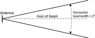
Figure 1.3 The horizontal beam width.
...Table of contents
- Cover image
- Title page
- Table of Contents
- Copyright
- Dedication
- Preface to the Third Edition
- Acknowledgements
- Chapter 1. Basic Radar Principles
- Chapter 2. The Radar System – Technical Principles
- Chapter 3. Target Detection
- Chapter 4. Automatic Radar Target Tracking, Specified Facilities
- Chapter 5. Automatic Identification System (AIS)
- Chapter 6. Operational Controls
- Chapter 7. Radar Plotting Including Collision Avoidance
- Chapter 8. Navigation Techniques Using Radar and ARPA
- Chapter 9. ARPA – Accuracy and Errors
- Chapter 10. Ancillary Equipment
- Chapter 11. Extracts from Official Publications
- Glossary of Acronyms and Abbreviations
- Index
Frequently asked questions
Yes, you can cancel anytime from the Subscription tab in your account settings on the Perlego website. Your subscription will stay active until the end of your current billing period. Learn how to cancel your subscription
No, books cannot be downloaded as external files, such as PDFs, for use outside of Perlego. However, you can download books within the Perlego app for offline reading on mobile or tablet. Learn how to download books offline
Perlego offers two plans: Essential and Complete
- Essential is ideal for learners and professionals who enjoy exploring a wide range of subjects. Access the Essential Library with 800,000+ trusted titles and best-sellers across business, personal growth, and the humanities. Includes unlimited reading time and Standard Read Aloud voice.
- Complete: Perfect for advanced learners and researchers needing full, unrestricted access. Unlock 1.5M+ books across hundreds of subjects, including academic and specialized titles. The Complete Plan also includes advanced features like Premium Read Aloud and Research Assistant.
We are an online textbook subscription service, where you can get access to an entire online library for less than the price of a single book per month. With over 1.5 million books across 990+ topics, we’ve got you covered! Learn about our mission
Look out for the read-aloud symbol on your next book to see if you can listen to it. The read-aloud tool reads text aloud for you, highlighting the text as it is being read. You can pause it, speed it up and slow it down. Learn more about Read Aloud
Yes! You can use the Perlego app on both iOS and Android devices to read anytime, anywhere — even offline. Perfect for commutes or when you’re on the go.
Please note we cannot support devices running on iOS 13 and Android 7 or earlier. Learn more about using the app
Please note we cannot support devices running on iOS 13 and Android 7 or earlier. Learn more about using the app
Yes, you can access Radar and ARPA Manual by Alan G. Bole,Alan D. Wall,Andy Norris in PDF and/or ePUB format, as well as other popular books in Technik & Maschinenbau & Elektrotechnik & Telekommunikation. We have over 1.5 million books available in our catalogue for you to explore.