- 520 pages
- English
- ePUB (mobile friendly)
- Available on iOS & Android
eBook - ePub
Radiation in Art and Archeometry
About this book
/inca/publications/misc/creaghcov.htmAbout the coverThis book contains twenty chapters covering a wide range of research in the fields of scientific conservation of art and archaeometry. The common thread is the use of radiation in these analyses. The term "radiation" is used in the widest possible sense. The book encompasses the use of electromagnetic radiation in its microwave, infrared, visible, ultraviolet, x ray and &ggr; ray forms and the use of particulate forms such as electrons, neutrons and charged particles for which the Planck's Law relation applies. In many cases there is an interplay between the two forms: for example, proton induced x ray emission (PIXE), secondary ion mass spectrometry (SIMS). As far as possible the chapters have been arranged in order of ascending particle energy. Thus it commences with the use of microwaves and finishes with the use of &ggr; rays. The authors were chosen on the basis of their expertise as practitioners of their particular field of study. This means that, for example, the mature fields of study such as the IR and UV study of paintings have been written by senior researchers, whereas for the emerging fields of synchrotron and neutron techniques the chapters have been written by talented researchers at the commencement of their careers.
Trusted by 375,005 students
Access to over 1.5 million titles for a fair monthly price.
Study more efficiently using our study tools.
Information
The use of ground-penetrating radar in archaeology
Lawrence B. Conyers, Department of Anthropology, University of Denver, 2130 S. Race Street, Denver, CO 80208
Ground-penetrating radar is a geophysical method that can accurately map buried archaeological features in three-dimensions. Data are collected when radar waves are transmitted from a surface antenna into the ground and reflected off buried archaeological features and stratigraphic horizons. The reflected waves are recorded back at the surface and the transmission time is measured, which can then be converted to depth in the ground. Digital data acquisition allows reflection profiles to be filtered and enhanced in order to produce high quality two-dimensional images. The spatial mapping of reflected wave amplitudes within a grid can be used to accurately map buried sites in three-dimensions.
1 INTRODUCTION
In today’s climate of rescue archaeology, cultural resource management and the prevalent ethic of site conservation, non-invasive methods of subsurface exploration and mapping are becoming increasingly important. With many archaeological excavation budgets severely restricted, and strict political and conservation considerations that must be considered, it is often not feasible or is undesirable to excavate large areas or randomly dig test excavations in the hope of finding buried archaeological sites. New computer enhanced geophysical methods, including ground-penetrating radar, are being developed for site identification, mapping and analysis, which can non-invasively gather massive amounts of data from buried sites without having to dig. Archaeologists who are only familiar with the traditional methods of gathering data by the shovel and trowel method are being increasingly marginalized in this changing environment.
Increasingly sophisticated ground-penetrating radar (GPR) acquisition and processing methods can be employed to gather important subsurface information in un-excavated areas including the location, depth and orientation of important buried features and artifacts, precluding the time consuming and costly process of digging. Maps and images produced from the GPR data can not only identify buried features for possible future excavation but also interpolate between excavations into the unknown, projecting archaeological knowledge into areas that have not yet been, or may never be excavated.
2 THE GROUND-PENETRATING RADAR METHOD
Ground-penetrating radar equipment is very portable, consisting of paired surface antennas, radar system and computer with monitor and keyboard (Figure 1). Power is supplied to the system by batteries, electrical generator or normal AC current.
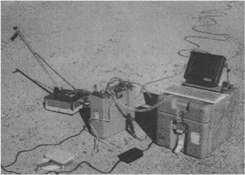
Figure 1 Ground-penetrating radar equipment including a 500 MHz antenna (with handle), radar generation system and hard drive, and computer monitor.
Data are acquired by reflecting radar waves, created by pulses from a surface antenna, off subsurface objects, features or bedding contacts. Reflections that are generated from buried features or stratigraphic changes are detected and recorded at a receiving antenna on the ground surface (Conyers and Goodman, 1997: 23 [1]). The elapsed time between when the pulse was sent and when a series of reflections, from progressively deeper in the ground, are received back at the surface is then measured and recorded.
Any change in the electrical or magnetic properties of features in the ground will cause a portion of the transmitted radar pulse to be reflected back to the surface. When the travel times of the energy pulses are measured, and their velocity through the ground can be determined, distance (or depth in the ground) can be accurately measured (Conyers and Lucius, 1996 [2]).
Reflection data are collected as both surface receiving and transmitting antennas are moved along the ground surface in tandem, while collecting a series of reflections in a linear transect. Each series of reflections recorded at one location on the ground is called a trace. When many traces along a transect are stacked vertically, they can be viewed as two-dimensional vertical reflection profiles of the subsurface stratigraphy and other buried features (Figure 2).
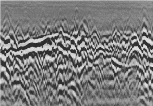
Figure 2 Ground-penetrating Radar Profile showing a buried living surface on the left side of the profile, which has been disturbed by anthropogenic disturbance on the right side of the profile. High amplitude reflections are dark black while areas of little reflection are gray.
Different antenna frequencies, ranging from about 80 to 1200 MHz are typically used in archaeological mapping (Conyers and Goodman, 1997: 40 [1]). The lower the antenna frequency, the longer the wavelength of energy transmitted into the ground. These longer radar wavelengths can penetrate quite deeply in the ground, but are only capable of resolving fairly large buried features. For instance, 80 MHz antennas may be able to transmit and then receive energy back at the surface from a depth of 3 meters or more, but are incapable of resolving features smaller than a few meters in diameter. In contrast, a 1,000 MHz antenna can transmit radar energy to at most 50 centimeters depth, but the resulting reflections can resolve objects as small as a few centimeters in diameter.
Some ground conditions are favorable for radar energy transmission, such as dry sand, volcanic ash or dry soils. The media most conducive for radar transmission are electrically resistive materials with little magnetic permeability (Conyers and Goodman, 1997: 53 [1]). In contrast, wet clay and any other material that is highly electrically conductive will readily attenuate radar waves as they penetrate into the ground and most energy will be lost near the ground surface, irrespective of antenna frequency or power.
As large data sets are acquired in a regular series of parallel and perpendicular transects within a grid, and the reflections derived in many two-dimensional profiles are correlated and processed, accurate three-dimensional maps of buried features and associated stratigraphy can be constructed. The physical and chemical changes of the buried materials can also be mapped because digital data measured in this three-dimensional volume of reflections includes the amplitudes of those reflected waves, which are indicative of the variations within the buried materials (Conyers and Goodman, 1997: 149 [1]). The higher the amplitude of the reflected waves, the greater the electrical and magnetic contrast that exists at the contact between contrasting materials in the ground. For instance, a very high amplitude reflection would typically be generated at the boundary between dry sand and wet clay, because they have very different electrical and magnetic properties. Often similar high amplitude reflections are generated at contacts between archaeological features, such as buried floors, and the surrounding materials.
3 THE HISTORY OF GPR DATA PROCESSING AND INTERPRETATION IN ARCHAEOLOGY
Ground-penetrating radar has been traditionally used as a method for identifying the presence or absence of buried archaeological features. Throughout the 1970s and 1980s its use was almost always as an exploration tool, with limited given to detailed subsurface mapping of those features or analysis of the surrounding stratigraphy. Only a limited amount of data processing was done, mostly because of the difficulty in processing and interpreting large GPR data sets that might contain many thousands of individual reflections, most of which were printed out as paper records in the field. In addition the complexity of radar reflections that can occur in the ground, the difficulty in identifying important reflections, and the massive amounts of data that are typically collected usually impeded any sophisticated data interpretation. In addition, the reflection profiles were usually un-processed “raw” data that contained an abundance of “noise”, which could be extraneous reflections from surface objects and even from people moving about in the vicinity of the antennas, complicating two-dimensional images. Fortunately, even in these types complex and “busy” data sets, significant reflection “anomalies” could usually be visually correlated with other similar reflections in adjacent profiles. In this type of rudimentary data analysis most archaeological features were identified visually, based only on what buried archaeological features were “thought” to look like. If buried reflection surfaces were extensive enough, reflections could sometimes be correlated from profile to profile within a grid, but often the abundance and complexity of detectable reflections precluded accurate correlation. In addition, without extensive testing and confirmation of the discovered features, little could actually be determined about the origin and spatial orientation of many reflections, and therefore most interpretation was usually quite subjective.
A huge breakthrough in GPR processing occurred in the late 1980s as digital recording methods allowed for post-acquisition data processing, filtering and manipulation of reflection records (Annan and Davis, 1992 [3]). These post-acquisition processing methods allowed background “noise”, a common problem in all GPR records, to be routinely removed from the recorded data (Conyers and Goodman, 1997: 77 [1]). Background noise, which produces the horizontal banding common in typical un-processed GPR profiles, is caused by noise inherent in GPR systems, “ringing” within antennas and multiple recorded reflections that occur as radar energy is repeatedly bounced between the antennas and the ground surface (Conyers and Goodman, 1997: 78 [1]). Multiple reflections can also occur within the housing of radar antennas and sometimes between surface features and the antennas. Computers can easily remove these horizontal bands by arithmetically averaging all recorded waves that were recorded at the same times within all the traces collected in a transect. This “average wave” can then be subtracted from each trace, leaving only those reflections that are non-horizontal and presumably those that were generated from important geological or archaeological features in the ground.
A s...
Table of contents
- Cover image
- Title page
- Table of Contents
- Copyright
- Preface
- Chapter 1: The use of ground-penetrating radar in archaeology
- Chapter 2: Electrochemical impedance measurements in the conservation of metals
- Chapter 3: The infrared examination of paintings
- Chapter 4: The ultraviolet and fluorescence study of paintings and manuscripts.
- Chapter 5: Raman Microscopy: A useful tool for the archaeometric analysis of pigments
- Chapter 6: Thermoluminescence Dating
- Chapter 7: Synchrotron Radiation Tomographic Energy-Dispersive Diffraction Imaging
- Chapter 8: The use of X-ray techniques for bone densitometry in archaeological skeletons
- Chapter 9: The role of SIMS in understanding ancient materials
- Chapter 10: Scanning electron microscopy techniques for imaging materials from paintings.
- Chapter 11: Transmission Electron Microscopy and its use for the study of paints and pigments
- Chapter 12: Radiocarbon dating in archaeology: methods and applications
- Chapter 13: X-ray Fluorescence Applications for the Study and Conservation of Cultural Heritage
- Chapter 14: A Synchrotron X-ray diffraction study of Egyptian cosmetics
- Chapter 15: Attribution of antique Chinese blue-and-white porcelains using Energy Dispersive X-Ray Fluorescence (EDXRF)
- Chapter 16: Neutron and synchrotron radiation studies of archaeological objects
- Chapter 17: The study of the characterisation and provenance of coins and other metalwork using XRF, PIXE and Activation Analysis
- Chapter 18: The use of Mössbauer Spectroscopy in studies of archaeological ceramics
- Chapter 19: AMS dating in archaeology, history and art
- Chapter 20: Dating beyond the radiocarbon barrier using U-series isotopes and trapped charges
- AUTHOR INDEX
- SUBJECT INDEX
Frequently asked questions
Yes, you can cancel anytime from the Subscription tab in your account settings on the Perlego website. Your subscription will stay active until the end of your current billing period. Learn how to cancel your subscription
No, books cannot be downloaded as external files, such as PDFs, for use outside of Perlego. However, you can download books within the Perlego app for offline reading on mobile or tablet. Learn how to download books offline
Perlego offers two plans: Essential and Complete
- Essential is ideal for learners and professionals who enjoy exploring a wide range of subjects. Access the Essential Library with 800,000+ trusted titles and best-sellers across business, personal growth, and the humanities. Includes unlimited reading time and Standard Read Aloud voice.
- Complete: Perfect for advanced learners and researchers needing full, unrestricted access. Unlock 1.5M+ books across hundreds of subjects, including academic and specialized titles. The Complete Plan also includes advanced features like Premium Read Aloud and Research Assistant.
We are an online textbook subscription service, where you can get access to an entire online library for less than the price of a single book per month. With over 1.5 million books across 990+ topics, we’ve got you covered! Learn about our mission
Look out for the read-aloud symbol on your next book to see if you can listen to it. The read-aloud tool reads text aloud for you, highlighting the text as it is being read. You can pause it, speed it up and slow it down. Learn more about Read Aloud
Yes! You can use the Perlego app on both iOS and Android devices to read anytime, anywhere — even offline. Perfect for commutes or when you’re on the go.
Please note we cannot support devices running on iOS 13 and Android 7 or earlier. Learn more about using the app
Please note we cannot support devices running on iOS 13 and Android 7 or earlier. Learn more about using the app
Yes, you can access Radiation in Art and Archeometry by D.C. Creagh,D.A. Bradley in PDF and/or ePUB format, as well as other popular books in Social Sciences & Physics. We have over 1.5 million books available in our catalogue for you to explore.