eBook - ePub
Circuit Design: Know It All
- 1,248 pages
- English
- ePUB (mobile friendly)
- Available on iOS & Android
eBook - ePub
Circuit Design: Know It All
About this book
The Newnes Know It All Series takes the best of what our authors have written to create hard-working desk references that will be an engineer's first port of call for key information, design techniques and rules of thumb. Guaranteed not to gather dust on a shelf!Electronics Engineers need to master a wide area of topics to excel. The Circuit Design Know It All covers every angle including semiconductors, IC Design and Fabrication, Computer-Aided Design, as well as Programmable Logic Design.
- A 360-degree view from our best-selling authors
- Topics include fundamentals, Analog, Linear, and Digital circuits
- The ultimate hard-working desk reference; all the essential information, techniques and tricks of the trade in one volume
Trusted by 375,005 students
Access to over 1.5 million titles for a fair monthly price.
Study more efficiently using our study tools.
Information
Chapter 1
The Fundamentals
1.1 Electrical Fundamentals
This chapter has been designed to provide you with the background knowledge required to help you understand the concepts introduced in the later chapters. If you have studied electrical science, electrical principles, or electronics then you will already be familiar with many of these concepts. If, on the other hand, you are returning to study or are a newcomer to electronics or electrical technology this chapter will help you get up to speed.
1.1.1 Fundamental Units
You will already know that the units that we now use to describe such things as length, mass and time are standardized within the International System of Units (SI). This SI system is based upon the seven fundamental units (see Table 1.1).
Table 1.1 SI units
| Quantity | Unit | Abbreviation |
| Current | ampere | A |
| Length | meter | m |
| Luminous intensity | candela | cd |
| Mass | kilogram | kg |
| Temperature | Kelvin | K |
| Time | second | s |
| Matter | mol | mol |
1.1.2 Derived Units
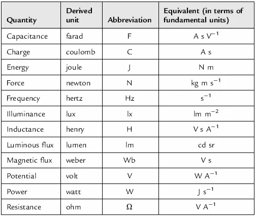
All other units are derived from these seven fundamental units. These derived units generally have their own names and those commonly encountered in electrical circuits are summarized in Table 1.2, together with the corresponding physical quantities.
Table 1.2 Electrical quantities
(Note that 0K is equal to −273°C and an interval of 1K is the same as an interval of 1°C.)
If you find the exponent notation shown in Table 1.2 a little confusing, just remember that V−1 is simply 1/V, s−1 is 1/s, m−2 is 1/m−2, and so on.
Example 1.1
The unit of flux density (the tesla) is defined as the magnetic flux per unit area. Express this in terms of the fundamental units.
Solution
The SI unit of flux is the weber (Wb). Area is directly proportional to length squared and, expressed in terms of the fundamental SI units, this is square meters (m2). Dividing the flux (Wb) by the area (m2) gives Wb/m2 or Wb m−2. Hence, in terms of the fundamental SI units, the tesla is expressed in Wb m−2.
Example 1.2
The unit of electrical potential, the volt (V), is defined as the difference in potential between two points in a conductor, which when carrying a current of one amp (A), dissipates a power of one watt (W). Express the volt (V) in terms of joules (J) and coulombs (C).
Solution
In terms of the derived units:

Note that: Watts = Joules/seconds and also that Amperes × seconds = Coulombs.
Alternatively, in terms of the symbols used to denote the units:

One volt is equivalent to one joule per coulomb.
1.1.3 Measuring Angles
You might think it strange to be concerned with angles in electrical circuits. The reason is simply that, in analog and AC circuits, signals are based on repetitive waves (often sinusoidal in shape). We can refer to a point on such a wave in one of two basic ways, either in terms of the time from the start of the cycle or in terms of the angle (a cycle starts at 0° and finishes as 360°—see Figure 1.1). In practice, it is often more convenient to use angles rather than time; however, the two methods of measurement are interchangeable and it’s important to be able to work in either of these units.
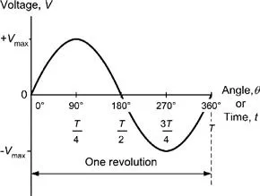
Figure 1.1 One cycle of a sine wave voltage
In electrical circuits, angles are measured in either degrees or radians (both of which are strictly dimensionless units). You will doubtless already be familiar with angular measure in degrees where one complete circular revolution is equivalent to an angular change of 360°. The alternative method of measuring angles, the radian, is defined somewhat differently. It is the angle subtended at the center of a circle by an arc having length that is equal to the radius of the circle (see Figure 1.2).
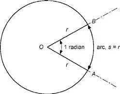
Figure 1.2 Definition of the radian
You may sometimes find that you need to convert from radians to degrees, and vice versa. A complete circular revolution is equivalent to a rotation of 360° or 2π radians (note that π is approximately equal to 3.142). Thus, one radian is equivalent to 360/2π degrees (or approximately 57.3°). Try to remember the following rules that will help you to convert angles expressed in degrees to radians and vice versa:
• From degrees to radians, divide by 57.3.
• From radians to degrees, multiply by 57.3.
Example 1.3
Express a quarter of a cycle revolution in terms of:
(a) degrees;
(b) radians.
So...
Table of contents
- Cover image
- Title page
- Table of Contents
- Copyright Page
- About the Authors
- Chapter 1. The Fundamentals
- Chapter 2. The Semiconductor Diode
- Chapter 3. Understanding Diodes and Their Problems
- Chapter 4. Bipolar Transistors
- Chapter 5. Transistors Field-Effect
- Chapter 6. Identifying and Avoiding Transistor Problems
- Chapter 7. Digital Circuit Fundamentals
- Chapter 8. Number Systems
- Chapter 9. Binary Data Manipulation
- Chapter 10. Combinational Logic Design
- Chapter 11. Sequential Logic Design
- Chapter 12. Memory
- Chapter 13. Selecting a Design Route
- Chapter 14. Designing with Logic ICs
- Chapter 15. Interfacing
- Chapter 16. DSP and Digital Filters
- Chapter 17. Dealing with High-Speed Logic
- Chapter 18. Bridging the Gap between Analog and Digital
- Chapter 19. Op-Amps
- Chapter 20. Analog-to-Digital Converters
- Chapter 21. Sensors
- Chapter 22. Active Filters
- Chapter 23. Radio-Frequency (RF) Circuits
- Chapter 24. Signal Sources
- Chapter 25. EDA Design Tools for Analog and RF
- Chapter 26. Useful Circuits
- Chapter 27. Programmable Logic to ASICs
- Chapter 28. Complex Programmable Logic Devices (CPLDs)
- Chapter 29. Field-Programmable Gate Arrays (FPGAs)
- Chapter 30. Design Automation and Testing for FPGAs
- Chapter 31. Integrating Processors onto FPGAs
- Chapter 32. Implementing Digital Filters in VHDL
- Chapter 33. Microprocessor and Microcontroller Overview
- Chapter 34. Microcontroller Toolbox
- Chapter 35. Power Supply Overview and Specifications
- Chapter 36. Input and Output Parameters
- Chapter 37. Batteries
- Chapter 38. Layout and Grounding for Analog and Digital Circuits
- Chapter 39. Safety
- Chapter 40. Design for Production
- Chapter 41. Testability
- Chapter 42. Reliability
- Chapter 43. Thermal Management
- APPENDIX A: Standards
- Index
Frequently asked questions
Yes, you can cancel anytime from the Subscription tab in your account settings on the Perlego website. Your subscription will stay active until the end of your current billing period. Learn how to cancel your subscription
No, books cannot be downloaded as external files, such as PDFs, for use outside of Perlego. However, you can download books within the Perlego app for offline reading on mobile or tablet. Learn how to download books offline
Perlego offers two plans: Essential and Complete
- Essential is ideal for learners and professionals who enjoy exploring a wide range of subjects. Access the Essential Library with 800,000+ trusted titles and best-sellers across business, personal growth, and the humanities. Includes unlimited reading time and Standard Read Aloud voice.
- Complete: Perfect for advanced learners and researchers needing full, unrestricted access. Unlock 1.5M+ books across hundreds of subjects, including academic and specialized titles. The Complete Plan also includes advanced features like Premium Read Aloud and Research Assistant.
We are an online textbook subscription service, where you can get access to an entire online library for less than the price of a single book per month. With over 1.5 million books across 990+ topics, we’ve got you covered! Learn about our mission
Look out for the read-aloud symbol on your next book to see if you can listen to it. The read-aloud tool reads text aloud for you, highlighting the text as it is being read. You can pause it, speed it up and slow it down. Learn more about Read Aloud
Yes! You can use the Perlego app on both iOS and Android devices to read anytime, anywhere — even offline. Perfect for commutes or when you’re on the go.
Please note we cannot support devices running on iOS 13 and Android 7 or earlier. Learn more about using the app
Please note we cannot support devices running on iOS 13 and Android 7 or earlier. Learn more about using the app
Yes, you can access Circuit Design: Know It All by Darren Ashby,Bonnie Baker,Ian Hickman,Walt Kester,Robert Pease,Tim Williams,Bob Zeidman in PDF and/or ePUB format, as well as other popular books in Technology & Engineering & Electrical Engineering & Telecommunications. We have over 1.5 million books available in our catalogue for you to explore.