Power systems have two components of apparent power: active and reactive power. Both components are necessary for functioning of electrical systems. The active power is the average power absorbed by the resistive load. The reactive power is the measure of energy exchange between the source and reactive power of load. Energy storage devices do not dissipate or supply power, but exchange power with the rest of system. Active power is the one that is converted to other forms of energy in the load yet reactive power is only responsible for magnetizing purposes. Power factor is a ratio depicting how much of the power supplied is real. The reactive current contribute in the value of the overall magnitude of current in transmission lines causing unnecessarily high line currents and low power factor. Since a low power factor means higher amount of apparent power need to be supplied by the utility company, thus the company must also use bigger generators, large transformers and thicker transmission/distribution lines. This requires a higher capital expenditure and operational cost which usually result in the cost being passed to the consumer.In this research, we seek to identify the effects of a low power factor on Swaziland Electricity Companys power supply system and recommend possible solutions to the problem. The results are useful in determining how to optimally deliver power to a load at a power factor that is reasonably close to unity, thus reducing the utilitys operational costs while increasing the quality of the service being supplied.

- 115 pages
- English
- ePUB (mobile friendly)
- Available on iOS & Android
eBook - ePub
Reactive Power Compensation
About this book
Trusted by 375,005 students
Access to over 1.5 million titles for a fair monthly price.
Study more efficiently using our study tools.
Information
CHAPTER 1: INTRODUCTION
1.1 Introduction to Research
AC electrical power system loads have resistive and reactive impedances. The electricity supply network therefore possesses an active and a reactive power component as a result of the characteristic of the load impendences [1]. The reactive component can be further subdivided into two states: a leading and lagging state. Leading reactive power comes as a result of the capacitive component of the load whereas lagging reactive power comes due to the inductive component of the load introducing a lagging phase shift in the network.
This gets us to the topic of interest, ‘Power Factor’. It is a ratio that tells us how much power from that being supplied by the utility is being actually used to do useful work by the customer. Figure 1.0 below shows this relationship in a form of a right angled power triangle.
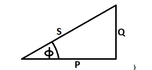
Figure 1.0: The Power Triangle [2].
Where:
S = apparent power (VA)
Q = reactive power (VAR)
P = real power (W)
Apparent power (S) is a complex combination of real power (P) and reactive power (Q). Real power, also called productive power does useful work and the reactive component of the power generates magnetic fields necessary for the operation of inductive devices such as AC motors, transformers etc. When in excess, reactive power can become detrimental to a power system as it greatly reduces the power factor, thus decreasing the distribution capacity while increasing the operational costs of the utility company.
1.2 Objectives
The main objectives of this project are:
- Identify the causes of a low PF in SEC’s power system paying special attention to the eastern side of the network.
- Calculate the power factor and the component values for the affected substations of SEC’s network.
- Evaluate the effects of a low power factor in SEC’s network.
- Draw conclusions and make recommendations for any modifications or improvements on PFC.
1.3 Significance of Research
Whenever a power system supplies power at a low power factor, a significant percentage of the power doesn’t do useful work at the load. This implies that the network is carrying higher current than required by load to cater for amount of reactive power in the network. The high transmission/distribution current result in increased system losses and voltage drops, thus reducing the power system’s capacity. Since Swaziland is currently importing around 70% of its power from neighboring countries in order to meet the demand of its customers, so correcting power factor will help in reducing this deficit. This research will serve as a guide on how to keep a power network operating at a power factor close to unity. Though this research is based mainly on SEC’s power system as it is where most of the work was done, the results are actually valid for nearly all power systems.
1.4 Problem Statement
The network of SEC has two injection points, Mahamba and Edwaleni. Mahamba supports the Eastern network while Edwaleni II is in the Western network. The customers in the Eastern network are mainly the agriculture industry with their major load being pumps for irrigation. In the west customers are nearly balanced between industrial and domestic, the load is mainly heating equipment, small motors, ventilation and cooling systems. This explains why the power factor of SEC’s network is not optimal in the eastern side of the system as it is extremely loaded with reactive power. With the company importing around 70% of its power from its neighboring countries, power factor problems should be always properly dealt with to ensure that what we have is utilized efficiently while trying to breach the gap on the amount that is being bought from Mozambique and South Africa.
Moreover, not only the system losses are increased when the system is operating at a low power factor, the voltage stability is also disturbed causing a drop in quality of supply as some electronic equipment are sensitive to voltage changes. Typically, the costs involved in installing power factor correction are paid back within a year or two and after that the savings will actually reduce the operational costs. On the other hand over-correction should be always avoided. This can be done through a thorough study and collection of enough relevant data about the network’s power factor before finalizing on a suitable method of correction and deciding on the component values.
1.5 Hypothesis
If we know the factors that contribute to the power factor being low and the load behavior of the affected portion of the network, then we can choose the appropriate PFC method to minimize the effects of those loads.
1.6 Layout of Thesis
Chapter two of this thesis discusses literature and theories behind power factor and its correction. Here we include the causes and effects of a low power factor in detail and how it is usually corrected in a power system.
In chapter three the research methodology used in the study will be described. The setting and the study design are also described. Here also the methods used to collect the data and the way the data will be analyzed are explained.
In chapter four, data on loading of five of SEC’s substations will be collected and used in calculating their power factor and the approximated size of correction equipment will be determined from the results.
Chapter five consist of the simulation model where the load behavior will be simulated and also the simulation results will be discussed here. The sixth chapter reviews the benefits of PFC and evaluates the cost and benefits associated with this project. Finally, chapter seven summarizes the research and also reveals the recommendations and conclusions made.
CHAPTER 2: LITERATURE REVIEW
2.1 Introduction
This chapter discusses the causes and effects of a low value of PF in an AC power network’s performance. It also outlines the need for power factor correction in affected parts of the power system and reviews the principles of operation for each of the methods of PFC discussed by the literature.
2.2 Power Factor
Power factor is the cosine of the angle between voltage and current of the power system. This angle is also equivalent to the angle of the network’s impedance. Consider the power triangle (Fig. 1.0), the power factor can be also expressed as a ratio of real power to apparent power. i.e.

Where
- Apparent power (S) is the complex summation of real and reactive power. It is a useful means of rating power equipment [3]. It can be further expressed as also a product of the circuit’s current and voltage or the square of c...
Table of contents
- Power Factor Correction
- Power Factor Correction
- ABSTRACT
- TABLE OF CONTENTS
- CHAPTER 1: INTRODUCTION
- CHAPTER 2: LITERATURE REVIEW
- CHAPTER 3: RESEARCH METHODOLOGY
- CHAPTER 4: DATA COLLECTION
- CHAPTER 5: RESULTS AND ANALYSIS OF THE SIMULATION MODEL
- CHAPTER 6: BENEFITS OF POWER FACTOR CORRECTION
- CHAPTER 7: FINDINGS, RECOMMENDATIONS AND CONCLUSIONS
- REFERENCES
- APPENDIXES
- Appendix A: Load Profiles
- Appendix B – Substations
- Appendix C : Simulation Results
Frequently asked questions
Yes, you can cancel anytime from the Subscription tab in your account settings on the Perlego website. Your subscription will stay active until the end of your current billing period. Learn how to cancel your subscription
No, books cannot be downloaded as external files, such as PDFs, for use outside of Perlego. However, you can download books within the Perlego app for offline reading on mobile or tablet. Learn how to download books offline
Perlego offers two plans: Essential and Complete
- Essential is ideal for learners and professionals who enjoy exploring a wide range of subjects. Access the Essential Library with 800,000+ trusted titles and best-sellers across business, personal growth, and the humanities. Includes unlimited reading time and Standard Read Aloud voice.
- Complete: Perfect for advanced learners and researchers needing full, unrestricted access. Unlock 1.5M+ books across hundreds of subjects, including academic and specialized titles. The Complete Plan also includes advanced features like Premium Read Aloud and Research Assistant.
We are an online textbook subscription service, where you can get access to an entire online library for less than the price of a single book per month. With over 1.5 million books across 990+ topics, we’ve got you covered! Learn about our mission
Look out for the read-aloud symbol on your next book to see if you can listen to it. The read-aloud tool reads text aloud for you, highlighting the text as it is being read. You can pause it, speed it up and slow it down. Learn more about Read Aloud
Yes! You can use the Perlego app on both iOS and Android devices to read anytime, anywhere — even offline. Perfect for commutes or when you’re on the go.
Please note we cannot support devices running on iOS 13 and Android 7 or earlier. Learn more about using the app
Please note we cannot support devices running on iOS 13 and Android 7 or earlier. Learn more about using the app
Yes, you can access Reactive Power Compensation by Dr. Hidaia Mahmood Alassouli in PDF and/or ePUB format, as well as other popular books in Technology & Engineering & Electrical Engineering & Telecommunications. We have over 1.5 million books available in our catalogue for you to explore.