![]()
1
Book Organization
Operators obtain information about the operation of the generator via a number of avenues:
• Panel annunciators
• Video display units fed from SCADA, DCS, or similar systems
• Computer printouts
• Gauges and meters at the control room (CR) or at the plant
• Alarms from monitoring or protection systems
• Protective device flags or signals
• Through the senses:
◦ Sound (e.g., abnormal noise emanating from the machine)
◦ Smell (e.g., smell of burning insulation, or ozone in open air-cooled generators)
◦ Sight (e.g., sparks on collector rings)
◦ Touch (e.g., excessive vibration of the turbine deck)
• Offline test results (e.g., IR,1 PI,2 Hipot,3 etc.)
• Online test results (e.g., TST,4 GITV,5 etc.)
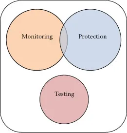
All of the aforementioned sources of information can be grouped as shown in Figure 1.1.
Plant engineers can obtain additional information, such as
• Machine history (equivalent operational hours; performed maintenance; previous faults; past operational events)
• Records related to sister units; known problems from OEM informational letters
• Pertinent information from technical literature, conference, and so forth
FIGURE 1.1
Operator sources of information about the condition of a given generator.
A succinct list of protective and monitoring functions will be presented in Chapters 2 and 3, respectively. Figure 1.1 shows that there is some gray area where protection and monitoring functions are shared. These will be described also in Chapters 2 and 3. Although tests are also advocated as being part of the troubleshooting tools, they are not covered in this book.
In addition to naming and briefly describing the typical generator protective functions, the purpose of Chapter 2 is mainly to illuminate the concept of protective zone. Understanding the protective zone concept, by which the reach of a given protective device is set, station personnel can optimize the effort of troubleshooting a given malfunction following a protection trip and/or alarm.
Chapter 3 incorporates a brief narrative describing available monitoring functions and techniques. The monitored parameters are a key input to Chapter 4, where the symptoms are described. While by definition protection is understood as a response to an abnormal condition that is too fast for operator intervention, monitoring is, on the other hand, the mechanism by which operators are appraised of a developing condition with their equipment, and can react properly with the purpose of resolving the issue with the generator online, or removing the unit from operation on a timely and deliberate basis. As it will be described in Chapter 3, a plethora of monitoring instrumentation translates into a more effective and opportune operator reaction to a developing anomaly. Obviously, there is a tradeoff between expenditure in monitoring capabilities and expected benefits.
Chapters 4 and 5 are the core of this book. Chapter 4 contains descriptions of all symptoms included in the book. By symptom it is meant an objective evidence of a physical disturbance indicating an abnormal and/or unexpected condition. Symptoms are primarily obtained from monitoring instrumentation or through the senses. One can also qualify flags, alarms, and trips from protective devices as symptoms; these are captured in Chapter 2 (“Protective Functions”). Chapter 6 contains descriptions of all malfunctions included in the book. By malfunction it is meant a degradation or failure of a function, process or component, so that it fails to perform correctly its designed-for duty. All symptoms and malfunctions are grouped in such a way that they fall under major generator components, such as stator, rotor, hydrogen systems, and so on.
Chapter 6 explains how symptoms and malfunctions may relate, and how these relationships can be taken advantage of, for the purpose of expediting troubleshooting.
Chapter 7 presents a number of ready-to-use forms that the operator and/or engineer can use to type in all the relevant variables that have alarm and trip values, so that they are handy during a troubleshooting activity.
Notes
1 IR—Insulation resistance.
2 PI—Polarization index.
3 Hipot—High potential test.
4 TST—Thermal sensitivity test.
5 GITV—Grid-induced torsional vibration measurements.
![]()
2
Protective Functions
2.1 Difference between Protection and Monitoring Functions
As explained in Chapter 1, oversight functions for the main generator can be classified as protection, monitoring, and testing. Testing simply indicates carrying out tests on the machine, mostly offline. The difference between protection and monitoring can be described best by the statement found in the 2014 release of the revised IEEE Std. 1129 [2].
Protection: The process of observing a system, and automatically initiating an action to mitigate the consequences of an operating condition that has deviated from established acceptable performance criteria, such as alarms, runbacks,1 and trips.
Monitoring: The process of observing a system by basic and advanced methods, with the purpose of verifying that its parameters lie within prescribed limits.
Some oversight functions are clearly identified as protective functions (e.g., sudden and large Volts/Hertz events and phase-to-phase short-circuits), because the event is too fast for the operator to react in time and execute a remedial action, and possible consequences too severe. Others, such as winding temperature and shaft voltage are clearly within the realm of monitoring, because they provide ample time for the operator to react and take defensive actions based on other information he/she gathers. Monitoring can also set alarms on, but automatic tripping is a distinctive feature of protection systems. There are a few that fall in the intersection of protection and monitoring. One such example is rotor vibration. If a trip value exists, it is almost always a high value, where operation of t...