Geared toward the HVAC professional, Practical Controls: A Guide to Mechanical Systems provides a solid foundation and well-rounded understanding of the role of controls in mechanical systems design and installation. This book takes a concise look at HVAC controls and controls methods - including electrical, electronic, and microprocessor-based controls and control systems. Using "real world" examples, it explores how various mechanical systems installed in today's facilities are best controlled. The text is a practical resource to controls contracting, providing basic rules, equipment guidelines, rules of thumb, pros and cons, and do's and don'ts.
- 469 pages
- English
- ePUB (mobile friendly)
- Available on iOS & Android
eBook - ePub
About this book
Trusted by 375,005 students
Access to over 1 million titles for a fair monthly price.
Study more efficiently using our study tools.
Information
Chapter 1
INTRODUCTION
Welcome! Unless you are reading this as a form of torture or as a cure for insomnia, you are most likely a member of the Heating, Ventilating, and Air Conditioning (HVAC) industry. How you became that could have been any number of ways. You may have fallen into it by accident, or you may have trained for a career in this industry. Regardless of how you got here, you are now part of a special club, a nationwide, better yet, a worldwide network of engineers, designers, technicians, and installers, all (most!) of whom are dedicated to providing “personal comfort,” through the proper and efficient application and utilization of mechanical equipment and systems.
You can call it what you want, but the HVAC industry is primarily a “mechanical” industry. The equipment and components that make up a typical HVAC system are mechanical in nature. Fans, pumps, dampers, valves, ductwork, and piping. Put ‘em all together and you have yourself a mechanical system. The designers of these systems, the mechanics that install them, and the technicians that work on them, are all trained in the mechanical vein.
How these systems are controlled, however, might very well fall under a different discipline, and is the very subject of this writing. An HVAC system can be described as being a mechanical system plus the control system that is required to properly and efficiently operate it. A typical mechanical system consists of many subsystems. Each of these subsystems in itself must be controlled. A fan must be “told” to turn on and off. A damper must be told when to be open, and when to be closed. A valve must be told what position to assume; whether to allow flow through it or not, or maybe to allow partial flow through it. To control any of one these subsystems on its own requires at least a little bit of insight, as to what function the subsystem is serving. More importantly, though, is how all of these various subsystems should work together, so as to operate as a single system.
It is the author’s intention to describe the role of controls in mechanical systems. This includes: how the various mechanical systems and subsystems should operate, how these systems should be designed to operate, and how to use “practical” controls methods to correctly control the operation of these systems. The first step to that end is to define what an HVAC system is. As stated earlier, an HVAC system can be thought of as a mechanical system plus the associated controls and control system required to operate it.
MECHANICAL SYSTEMS
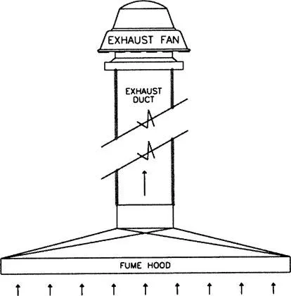
In HVAC, mechanical systems are typically designed to perform heating, cooling, and ventilation of spaces requiring such types of environmental control. The complexity of these systems ranges from the simple to the sophisticated. A ducted exhaust fan, that is manually turned on and off, is an example of a simple mechanical system. The system is composed of the fan, and the associated distribution ductwork required to convey the air, from the space being exhausted, to the outdoors (Figure 1-1a).
As an example of a more complicated mechanical system, consider Figure 1-1b: a hot water piping/pumping system consisting of two hot water boilers, two hot water circulating pumps, and the required hot water distribution piping going out to miscellaneous hydronic (hot water) heating equipment.
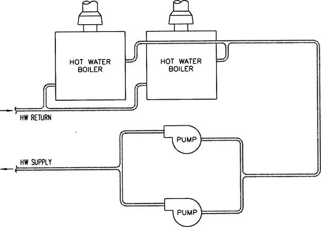
In each of the above examples of mechanical systems, we notice two distinct components: the equipment, and the required mechanical means of connecting the equipment, to other equipment, and to the real world. In the simple example of the exhaust system, the exhaust fan is the equipment, and the ductwork is the mechanical means. In the more complex example, the equipment consists of the boilers, pumps, and the miscellaneous heaters. The mechanical means of connecting together all of the equipment, in some meaningful manner, is the hot water piping.
We can say that mechanical systems are typically made up of these two components: the equipment, and the mechanical means of connecting the equipment. In all but the simplest of mechanical systems, equipment alone does not make up the system. Unless designed and manufactured as completely “stand-alone,” a piece of equipment does not do much good by itself. An example of a stand-alone piece of equipment would be perhaps an electric heater that you just plug into a wall outlet, or an oscillating fan that you might buy for your basement. For the majority of heating, ventilating, and air conditioning applications that are encountered in our industry, we’re talking systems. We, as specifiers and designers, are selecting equipment and designing the systems, integrating the equipment with properly designed mechanical distribution (ductwork and piping) systems that enable the equipment to function the way that it’s intended to: as part of a system!
Okay, okay. Enough talk about equipment, ductwork, and piping already! Time to switch gears and talk about the other component of a typical HVAC system: the controls!
CONTROLS AND CONTROL SYSTEMS
In our two examples of mechanical systems, we need some method of control. First and foremost, we need to have some idea, some inkling, of how the system should be controlled. The designing engineer of a mechanical system should have an idea of the system’s method of control, as he is the one designing it. As the designer of the system, the engineer may choose to write a description of how he would like the system to operate. This description, commonly referred to as a Sequence of Operation, should describe in detail how each piece of equipment and each subsystem should operate, so that the system as a whole is properly functional.
For the exhaust system example, it’s a no-brainer. The sequence of operation for this system may read as follows:
Fume hood exhaust fan EF-1 is manually operated by a user switch, located in the space being served by the fan.
For the hot water system example, however, the sequence of operation is not that simple and straightforward. For this example, it is extremely important that the engineer’s intentions be communicated to the control systems designer. When should the system be in operation? Is it seasonal? How are the pumps controlled? Does one run, with the other serving as a backup? Should the backup pump automatically start upon failure of the primary pump? How are the boilers controlled? By a single controller? Is hot water setpoint to be “reset” as a function of outside air temperature?
The engineer’s intentions for the operation of the system can be communicated in several different ways, or a combination of ways. He can choose to create a sequence of operation. He can specify certain controls or controls methods in his design. He can provide informative clues in his selection and sizing of equipment. And he can communicate his intentions verbally. For the hot water system example, the general sequence of operation may read like this:
Hot water system to be in operation whenever the outside air temperature is below 60 degrees F. (adj.). System enable/disable to be performed automatically, by an outside air temperature controller. When enabled, the pump selected as the “primary” pump is to run continuously. Selection of the primary pump is a manual procedure, performed by a primary pump selector switch. Upon failure of the primary pump, the backup pump is to automatically start. Boilers are to operate, via a common temperature controller, to maintain hot water temperature setpoint. Setpoint is to be a function of outside air temperature. As the outside air temperature increases, the hot water temperature setpoint is “reset” downwards. Miscellaneous unitary hot water heating equipment throughout the building is to operate via integral controls, to maintain desired comfort levels.
With the operation of the mechanical system described as such, the control systems designer has a clear direction to follow, and can design his or her control system in accordance with the sequence. During the design phase, the designer may also choose to elaborate on this given sequence of operation, so as to include important operational details, temperature settings, equipment specific information, etc.
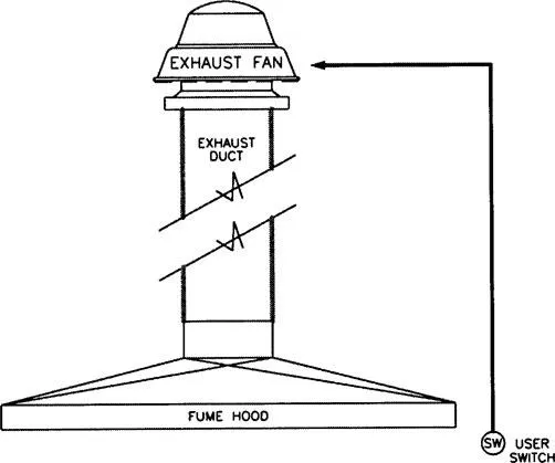
Now that the sequence of operation has been developed, the next step is to identify the various “points of control.” For the first example, this is a relatively simple task. By looking at the sequence, we gather that the “point of control” is a user switch located in the space served by the exhaust fan. In this case, the control device is a switch, that is used to manually turn the exhaust fan on and off (Figure 1-2a).
For the second example, identifying the points of control is a more complicated task. Figure 1-2b shows the various points of control required for the hot water system. The first point that we can identify is the outside air temperature controller. This device is to allow the hot water system to operate when the outside air temperature is below 60, and disallow its operation otherwise. In essence, the device is nothing more than a temperature actuated switch that closes when the temperature drops below the setpoint of the device. When the switch is closed, the primary pump runs, and the boilers are enabled for operation.
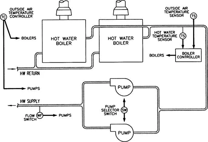
The second point that we can identify from the sequence of operation is the primary pump selector switch. The switch is a manual control that determines which of the two pumps is to be the primary pump. Another point that is associated with the pumps, that is perhaps a bit more difficult to identify, has to do with determining primary pump failure. The sequence states that the backup pump is to automatically start upon failure of the primary pump. How do we determine that the primary pump has failed? We can look at a couple of different things. We can monitor water flow with a flow switch, or we can monitor the pump motor’s current draw with a current sensing switch. Either device can alert us to a failure of the primary pump.
The final point of control that remains to be identified here, is that of hot water temperature control. The sequence mentions that the boilers are to be operated, by a common controller, to maintain hot water temperature setpoint. As such, we need to measure, or sense, the hot water supply temperature, common to both boilers, and also establish a means of controlling the operation of the boilers to maintain some setpoint. In simple terms, we are talking about installing a sensor in the common hot water supply piping, and transmitting the temperature “signal” to some central controller. At the controller, we have a means of establishing a setpoint. The controller can therefore calculate the difference in sensed temperature and setpoint, and stage the boilers accordingly, in an attempt to minimize this difference. This particular controller, as implied in the sequence, must also be able to reset the hot water temperature setpoint as a function of outside air temperature.
The next step in designing a control system for our given mechanical system is to begin selecting practical, “real-world” methods and controls to implement our sequence of operation. A mechanical system can be designed and a sequence of operation can be written in advance. On paper, and in theory, what is designed mechanically and what is written may be quite feasible. Yet in practice, what is being asked for the mechanical system to do by the sequence of operation may be impractical, inappropriate, or even impossible! This especially holds true for systems consisting of many subsystems. While each subsystem may be able to be controlled adequately on its own, the specified mode of operation for each of these individual subsystems may be counteractive to overall system operation.
The upcoming chapters will discuss many of the common mechanical systems that are popular in this day and age, and will attempt to define “practical” methods of control for e...
Table of contents
- Cover
- Half Title
- Title Page
- Copyright Page
- Dedication
- Table of Contents
- Forward
- Chapter 1 Introduction
- Chapter 2 Mechanical Systems and Equipment Overview
- Chapter 3 Introduction to Controls: Methods of Control
- Chapter 4 Sensors and Controllers
- Chapter 5 End Devices
- Chapter 6 Common Control Schemes
- Chapter 7 Intermission
- Chapter 8 Rooftop Units
- Chapter 9 Make-up Air Units
- Chapter 10 Fan Coil Units
- Chapter 11 Built Up Air Handling Units
- Chapter 12 RTU Zoning Systems and Stand-alone Zone Dampers
- Chapter 13 VAV and Fan Powered Boxes
- Chapter 14 Reheat Coils
- Chapter 15 Exhaust Fans and Systems
- Chapter 16 Pumps and Pumping Systems
- Chapter 17 Boilers
- Chapter 18 Chillers
- Chapter 19 Heat Exchangers
- Chapter 20 Humidifiers
- Chapter 21 Unitary Heating Equipment
- Chapter 22 Computer Room A/C Systems
- Chapter 23 Water Cooled Systems
- Chapter 24 Conclusion
- Appendices
- Index
Frequently asked questions
Yes, you can cancel anytime from the Subscription tab in your account settings on the Perlego website. Your subscription will stay active until the end of your current billing period. Learn how to cancel your subscription
No, books cannot be downloaded as external files, such as PDFs, for use outside of Perlego. However, you can download books within the Perlego app for offline reading on mobile or tablet. Learn how to download books offline
Perlego offers two plans: Essential and Complete
- Essential is ideal for learners and professionals who enjoy exploring a wide range of subjects. Access the Essential Library with 800,000+ trusted titles and best-sellers across business, personal growth, and the humanities. Includes unlimited reading time and Standard Read Aloud voice.
- Complete: Perfect for advanced learners and researchers needing full, unrestricted access. Unlock 1.4M+ books across hundreds of subjects, including academic and specialized titles. The Complete Plan also includes advanced features like Premium Read Aloud and Research Assistant.
We are an online textbook subscription service, where you can get access to an entire online library for less than the price of a single book per month. With over 1 million books across 990+ topics, we’ve got you covered! Learn about our mission
Look out for the read-aloud symbol on your next book to see if you can listen to it. The read-aloud tool reads text aloud for you, highlighting the text as it is being read. You can pause it, speed it up and slow it down. Learn more about Read Aloud
Yes! You can use the Perlego app on both iOS and Android devices to read anytime, anywhere — even offline. Perfect for commutes or when you’re on the go.
Please note we cannot support devices running on iOS 13 and Android 7 or earlier. Learn more about using the app
Please note we cannot support devices running on iOS 13 and Android 7 or earlier. Learn more about using the app
Yes, you can access Practical Controls by Steven R. Calabrese in PDF and/or ePUB format, as well as other popular books in Physical Sciences & Mechanics. We have over one million books available in our catalogue for you to explore.