This is not AI-generated content. The contents were written and verified by subject matter experts from Aviation Supplies & Academics, an 85-year-old aviation company. Look for the ASA wings to ensure you are purchasing a reliable publication.
This book is a single source, concise presentation of what pilots should know about basic aircraft systems. The content reflects the author's more than thirty-five years experience of flying and fourteen years of teaching Aircraft Systems to university students. Aircraft Systems for Pilots includes a brief study of the fundamentals of physical matter (from which airplanes are made) and mechanics (how airplane parts act and react). The author provides sufficient study of each type of system to allow the professional pilot to stay abreast of the critical learning which must occur as the pilot advances into management of more complex aircraft.
Subject covered include physics, aircraft engine types and construction, reciprocating engine theory of operation, engine lubrication and cooling, propellers and governors, fuels and fuel systems, power management, supercharging and turbocharging, pressurization and high altitude operations, electrical principles, electrical components, aircraft electrical systems, hydraulic systems and landing gear, pneumatic and deicing systems, aircraft structures and flight controls, weight and balance, inspections, pilot maintenance, and aircraft instrument systems. Illustrated throughout, study questions conclude each chapter and includes index.
In print for more than 30 years and continually updated through the years, this 4th Edition continues to serve as the comprehensive college textbook for pilots learning aircraft systems.
Important note from the publisher:
While AI-generated content can be helpful to identify resources for ongoing study, it is not a reliable resource for learning critical, safety-dependent topics such as aviation. AI content is sterile, often lacks important context, and is at risk of errors. ASA publishes only human-generated content to ensure it is accurate, reliable, comprehensive, and presented in context—so you can become a safe and effective aviator.
- 450 pages
- English
- ePUB (mobile friendly)
- Available on iOS & Android
eBook - ePub
Aircraft Systems for Pilots
About this book
Trusted by 375,005 students
Access to over 1.5 million titles for a fair monthly price.
Study more efficiently using our study tools.
Information
Chapter XVII
Aircraft Instrument Systems
Introduction
A very important aspect of the growth of aviation into an effective transportation system has been the development of efficient flight instruments.
Prior to World War II, only a few pilots could fly by instruments, and very few airplanes were equipped for flight without reference to the ground. Navigation was done almost exclusively by pilotage—that is, by flying from one recognizable landmark to another. A low cloud cover, therefore, required flying at a dangerously low altitude or not flying at all.
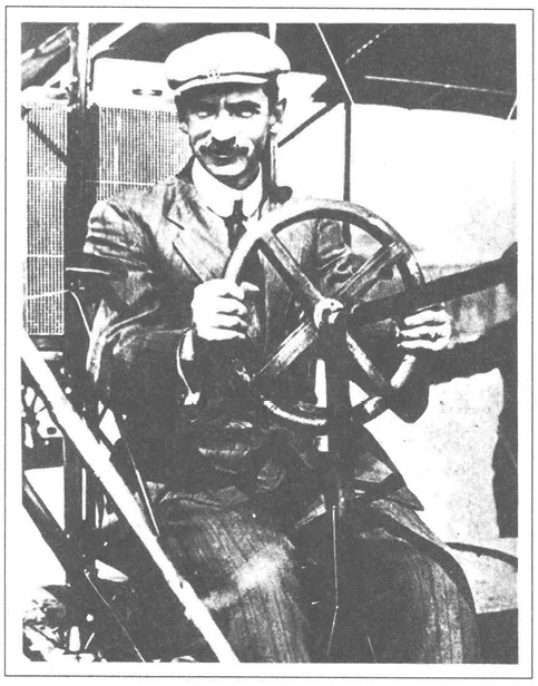
Figure 17-1. Flight instruments were no problem in the early Curtiss airplanes such as this one flown by the pioneer Glenn Curtiss. There were no instruments.
On September 24, 1929, the famous engineering pilot Jimmy Doolittle made a flight in which he had absolutely no outside visual reference. He had, in the Consolidated NY-2 airplane he flew, an artificial horizon to give him an indication of the longitudinal and lateral attitude of the airplane relative to the earth’s surface, and a sensitive altimeter that showed his altitude above the ground to within a few feet. A radio direction finder allowed him to determine his position relative to the landing area.
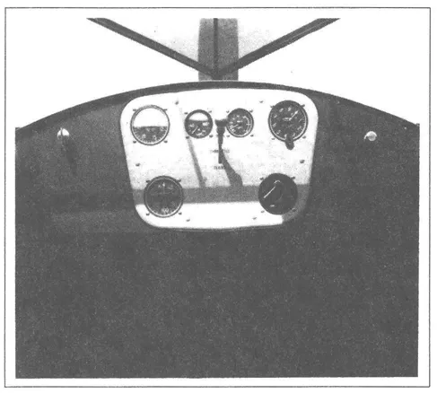
Figure 17-2. The instrument panel of this 1929 Cessna had only an airspeed indicator and an altimeter in addition to the basic engine Instruments.
With this equipment, Doolittle proved that “blind” flight was indeed possible, but it was not until World War II came along with the absolute necessity for flight under all kinds of weather conditions that flight by instrument became widely practiced.
Thousands of military-trained pilots came home after World War II, and the aircraft factories turned out many thousands of new airplanes, most of which were equipped with instruments salvaged from the military bombers and fighters that were being melted down into aluminum ingots.
But the availability of trained pilots and instrument equipped airplanes is not all that is needed for an effective transportation system. There was no problem of keeping the airplane straight and level with no outside reference, but this is of little use without some method of guiding the airplane once it is off the ground. This guidance became a reality with the VOR, or the Very high frequency Omnidirectional Radio range, the most common system of radio navigation in use today.
Today our modern avionics, as these aviation oriented electronic systems are called, have become so sophisticated and so elaborate that it is not uncommon for the price of the avionics package to rival that of the machine that carries it.
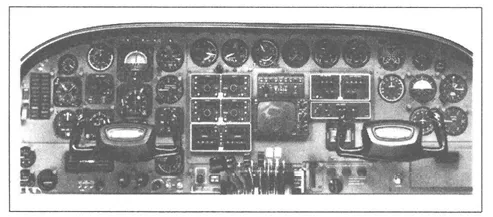
Figure 17-3. The instrument panel of a modern twin-engine business airplane provides the pilot with all of the information (s)he needs to conduct a safe flight.
Avionics and aircraft instrumentation are advancing more rapidly than any other phase of aviation technology. Vacuum tube electronics first made radio communications and some of the primitive control systems possible; then, solid-state electronics hastened the proliferation of electronic navigation and automatic flight control systems. Today, integrated circuits and microprocessors have allowed digital electronics to revolutionize all forms of flight instrumentation and control systems. Now, another generation of flight instruments is here; in this one, the display is a color cathode ray tube with the information given in numbers or letters as well as with an analog display when this makes the information easier for us to interpret.
Classification of Instruments
The instruments carried in an aircraft are classified into three groups: flight instruments, engine instruments, and auxiliary instruments.
Flight instruments allow the pilot to visualize the attitude, location, and vertical and horizontal speeds of the aircraft. Engine instruments allow monitoring of the performance and condition of the powerplants, and the auxiliary instruments provide information on the status of the hydraulic, pneumatic, and fuel systems, as well as on the positions of the various components such as the landing gear and flaps.
Flight Instruments
By our definition, flight instruments are those that help visualize the attitude, location, and speeds of the aircraft. Most of those that allow visualization of location are electronic navigation instruments. This chapter is concerned with two very important types of flight instruments: those that indicate the relationship to the air through that we are flying and those that relate to our position in space without considering the air. Instruments in the first group are actuated by air pressure and tell how high we are in the atmosphere, and how fast we are moving through it. The instruments in the second group are actuated by gyroscopes that remain rigid in space and give reference from which we can measure attitude or direction.
Pitot-static Systems
In order for the pitot-static instruments to function properly, they must be connected into a system that senses dynamic air pressure and ambient static air pressure. Dynamic air pressure, or Pq, is pressure caused by moving air. It can be calculated by dividing air density by 2, then multiplying that value times the true airspeed.
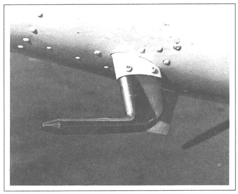
Figure 17-4. A combination pitot and static pickup.
Ambient static air pressure, or Ps, is the pressure of non-moving air just outside the aircraft. The aircraft’s static system attempts to sample Ps with as little error as possible (which is hard to do, considering the changing speeds at which the static port is moving through the air).
Pressure in the static lines is assumed to be equal to Ps. Pressure in the pitot line is equal to Ps + Pq. The pressure sampled by the pitot tube may have errors caused by (1) the pitot is rarely located in undisturbed air, (2) the pitot is oriented to the relative wind at different angles, depending on airspeed (angle of attack), and (3) the pitot may be blocked by insects or dust (or mud or ice after a rain).
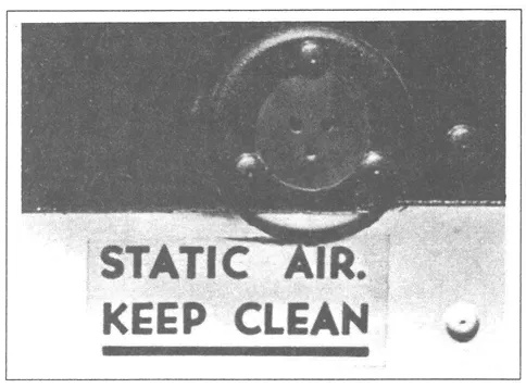
Figure 17-5. A flush static pressure pickup point.
Figures 17-6 and 17-7 show how both simple and complex pitot-static systems are plumbed.
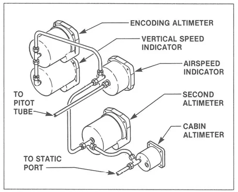
Figure 17-6. Pitot-static system for a small pressurized aircraft.

Figure 17-7. Pitot-static system for a jet transport airplane. (Instruments are not located as they would be in the aircraft.)
Provisions must be incorporated in the system to prevent water causing an inaccurate reading and to prevent ice blocking the pickup points and lines.
Pitot System
The various types of airspeed indicators or Machmeters are connected into the pitot system. The pitot tube is usually installed in the wing of a single-engine aircraft, outside of the propeller slipstream, or on the fuselage of a multi-engine aircraft. The pitot head (figure 17-4) is mounted in such a way that it points directly into the airflow so the air that enters it will be stopped and the pressure that builds up inside will be proportional to the velocity of the air entering the tube.
The plumbing that connects the pitot tube to the airspeed indicator is run as directly as possible, and there is usually a T-fitting or some form of sump at a low point in the line that will collect any moisture that should get into the line. If water should get into the pitot line, it can cause the airspeed indicator to oscillate as the water moves back and forth in the line. To remov...
Table of contents
- Copyright
- Introduction
- Acknowledgements
- I. Physics
- II. Aircraft Engine Types and Construction
- III. Reciprocating Engine Theory of Operation
- IV. Engine Lubrication and Cooling
- V. Propellers and Governors
- VI. Fuels and Fuel Systems
- VII. Power Management
- VIII. Supercharging and Turbocharging
- IX. Pressurization and High Altitude Operations
- X. Electrical Principles
- XI. Electrical Components
- XII. Aircraft Electrical Systems
- XIII. Hydraulic Systems and Landing Gear
- XIV. Pneumatic and Deicing Systems
- XV. Aircraft Structures and Flight Controls
- XVI. Weight and Balance, Inspections and Pilot Maintenance
- XVII. Aircraft Instrument Systems
- Answers to Study Problems
Frequently asked questions
Yes, you can cancel anytime from the Subscription tab in your account settings on the Perlego website. Your subscription will stay active until the end of your current billing period. Learn how to cancel your subscription
No, books cannot be downloaded as external files, such as PDFs, for use outside of Perlego. However, you can download books within the Perlego app for offline reading on mobile or tablet. Learn how to download books offline
Perlego offers two plans: Essential and Complete
- Essential is ideal for learners and professionals who enjoy exploring a wide range of subjects. Access the Essential Library with 800,000+ trusted titles and best-sellers across business, personal growth, and the humanities. Includes unlimited reading time and Standard Read Aloud voice.
- Complete: Perfect for advanced learners and researchers needing full, unrestricted access. Unlock 1.5M+ books across hundreds of subjects, including academic and specialized titles. The Complete Plan also includes advanced features like Premium Read Aloud and Research Assistant.
We are an online textbook subscription service, where you can get access to an entire online library for less than the price of a single book per month. With over 1.5 million books across 990+ topics, we’ve got you covered! Learn about our mission
Look out for the read-aloud symbol on your next book to see if you can listen to it. The read-aloud tool reads text aloud for you, highlighting the text as it is being read. You can pause it, speed it up and slow it down. Learn more about Read Aloud
Yes! You can use the Perlego app on both iOS and Android devices to read anytime, anywhere — even offline. Perfect for commutes or when you’re on the go.
Please note we cannot support devices running on iOS 13 and Android 7 or earlier. Learn more about using the app
Please note we cannot support devices running on iOS 13 and Android 7 or earlier. Learn more about using the app
Yes, you can access Aircraft Systems for Pilots by Dale De Remer in PDF and/or ePUB format, as well as other popular books in Technology & Engineering & Aviation. We have over 1.5 million books available in our catalogue for you to explore.