![]()
![]()
Chapter 1
Instruments and Systems
The definitions and regulations regarding day visual meteorological conditions (VMC) and night VMC do not specify a clearly defined horizon. Night flight is instrument flight—make no mistake. If there is no visual horizon, you are flying on the clocks. During the day in reduced visibility and over level terrain, you may get away with a vertical reference below the airplane as a guide to airplane attitude and flight path. At night, it is too risky. Uneven distribution of lights and stars gives subtle but misleading cues as to which way is up, which way is down, and whether or not the airplane is level. You must fly attitude on instruments and be able to do so competently when talking on the radio, reading charts, writing down instructions, and looking for ground features and other traffic.
Flight instruments fall functionally into three categories: pressure instruments, gyroscopic instruments, and compass instruments. Pressure instruments include the airspeed indicator (ASI), the altimeter, and the vertical speed indicator (VSI). Gyroscopic instruments include the attitude indicator (AI), the heading indicator (HI), and the turn indicator or turn coordinator. Compass instruments use a magnetic reference. In support of the flight instruments are the pitot-static system, the vacuum system, and the electrical system. All of these are brought together by the greatest aid to the pilot—the autopilot.
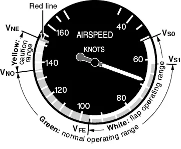
The airspeed indicator displays indicated airspeed (IAS). Indicated airspeed is a measure of dynamic pressure, which is the difference between the total pressure of the pitot head and the ambient static pressure. The airspeed indicator will have the following specific speeds marked on it:
- VS0—stall speed at maximum weight, landing gear down, flaps down, power off;
- VS1—stall speed at maximum weight, landing gear up, flaps up, power off;
- VFE—maximum speed, flaps extended;
- VNO—maximum structural cruise speed (for normal operations); and
- VNE—never-exceed speed (maximum speed, all operations).
Figure 1-1 ASI.
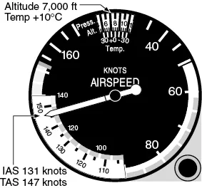
In addition to showing indicated airspeed, some airspeed indicators are able to show true airspeed (TAS). These ASIs have a manually rotatable scale to set outside air temperature (OAT) against altitude, allowing the pilot to read TAS as well as IAS.
Figure 1-2 IAS/TAS indicator.
Airspeed Indicator Errors
Density Error
Density error occurs any time an airplane is flying in conditions that are other than standard atmospheric conditions (ISA) at sea level. This is why the airspeed indicator does not indicate TAS.
Compressibility Error
Compressibility error increases with airspeed but is only relevant above 200 knots.
Position Error
Position error occurs because of pitot-static system errors. Errors vary with speed and attitude and include maneuver-induced errors. Pressure error correction (PEC) is shown in the pilot’s operating handbook. Indicated airspeed corrected for pressure and instrument error is called calibrated airspeed (CAS).
Instrument Error
Instrument error is caused by small manufacturing imperfections and the large mechanical amplification necessary for small, sensed movements. Instrument error is insignificant in general aviation (GA) airplanes.
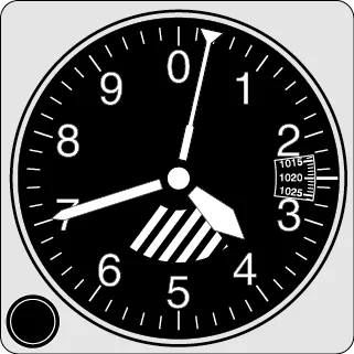
Altimeter
The altimeter converts static pressure at the level of the airplane to register vertical distance from a datum (the reference from which a measurement is made). At lower altitudes, a one inch decrease in pressure indicates approximately 1,000 feet gain in altitude. For all operations in the U.S. below 18,000 feet, the local altimeter setting is used. Since the height of terrain and obstacles shown on a chart is above mean sea level (MSL), this becomes your altitude reference. At or above 18,000 feet MSL, standard pressure (29.92 in. Hg) is set and flight levels are reported to the nearest 100 feet (e.g. 11,500 feet is FL115), although cruising levels are usually whole thousands of feet (e.g. FL120). For all operations below 18,000 feet (the transition altitude), pilots are required to use the current local altimeter setting and then set 29.92 in. Hg when climbing through 18,000 feet. The setting is changed from standard pressure to the local altimeter setting when descending through FL180 (the transition level).
Figure 1-3 Altimeter.
At or above 18,000 feet MSL, set 29.92 in. Hg in the pressure window. Below 18,000 feet MSL, set the local altimeter setting in the pressure window.
Altimeter Errors
Barometric Error
Barometric error is induced in an altimeter when atmospheric pressure at sea level differs from standard atmospheric conditions. The correct setting of the barometric subscale removes the error.
Temperature Error
Temperature error is induced when the temperature (density) differs from standard atmospheric conditions. Note that there is no adjustment.
Position Error
Position error occurs because of static system errors and is minor. Errors vary with speed and attitude and include maneuver-induced errors.
Instrument Error
Instrument error is caused by small manufacturing imperfections and is insignificant.
Lag
Lag occurs when the response of the capsule and linkage is not instantaneous. The altimeter reading lags slightly when altitude is increased or decreased rapidly.
Altimeter Check
Whenever an accurate local altimeter setting is available and the airplane is at an airfield with a known elevation, pilots must conduct an accuracy check of the altimeter before takeoff. The altimeter is checked by comparing its indicated altitude to a known elevation using an accurate local altimeter sett...