The English Industrial Revolution was a triumph of ingenuity and invention. New sources of power, better manufacturing methods and expanding transport systems brought fantastic changes affecting every walk of life. Man and machine worked side by side to produce iron, coal and cotton cloth on a scale never before imagined. In this easy-to-follow and carefully researched book, Stan Yorke explains the machines and processes that helped to create our industrial world, using drawings and diagrams by his son, Trevor. Four major industrial areas are examined: the waterwheel as a source of power in mills and foundries; the steam engine which made power available to a variety of manufacturing industries; the mechanisation of textile production making cloth for all a reality; and iron, which revolutionised bridge construction and made the railways possible. There are now over 500 museums related to industry in the British Isles and information on where to find them is contained in the book.
- 128 pages
- English
- ePUB (mobile friendly)
- Available on iOS & Android
eBook - ePub
About this book
Trusted by 375,005 students
Access to over 1.5 million titles for a fair monthly price.
Study more efficiently using our study tools.
Information
Subtopic
19th Century HistoryIndex
HistorySECTION II
STARS
OF THE
SHOW

CHAPTER 3
Wheels from the Past
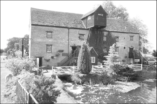
FIG 3.1: The quintessential mill. This is Barnwell Mill on the river Nene in Cambridgeshire, now converted to a restaurant but once a busy flour mill with at least two breastshot waterwheels.
You may well ask why I have chosen this subject at all since waterwheels existed long before the Industrial Revolution. The fact is that they were still our main source of power even at the beginning of the 18th century and without the waterwheel the revolution simply could not have happened.
The earliest waterwheels were the Norse wheels, which worked like a simple turbine. They turned a vertical shaft, so the grinding stones could be directly driven. There are, however, no examples left in England.
The normal type of waterwheel is known as a Vitruvius wheel, named after the Roman engineer who first described them. Their design involved a quite complex balance between diameter, width and the features of the river water they used. Rivers, unfortunately, do not flow steadily all year round, a problem that was partly solved by building a weir across the river to hold back a considerable length of water – the mill pond. From one end of this pond a channel would be created, which fed the waterwheel.
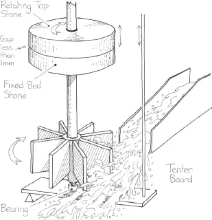
FIG 3.2: Diagrammatic view of the early Norse wheel. These were basic turbines, which were to reappear many centuries later in a much more sophisticated form. The grindstones would have been smaller than we are used to seeing today.
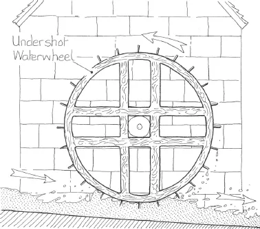
FIG 3.3: The basic Vitruvius undershot waterwheel. Though the path of the water can be constrained so that all the water must pass under the wheel, this is little more than a Norse wheel on its side. Its much larger diameter, however, allows the shaft to be kept well above the stream. Relatively easy to build and maintain.
This simple idea brought two desirable features: it allowed great quantities of flood water to pass over the weir in winter without raising the mill pond water level too much, and the feed channel (leat or leete) allowed the water flow to the wheel to be controlled or indeed turned off completely.
The design of the wheel itself was governed by three factors: how far the water had to fall (determined by the weir height); how much water was available; and the strength of the materials, in particular, the main shaft that conveyed the rotating energy from the wheel into the mill. Early wheels tended to be two to three metres in diameter and no more than one metre wide. Most were undershot, where the speed of the water matters, or breastshot, where the weight of the water provides most of the energy. There was a basic limit on the torque that could be carried along the wooden shaft without it breaking and this limited the size of the early wheels. Where the water supply was plentiful, it was the usual practice to build more than one wheel within the same mill building, all fed from the same mill pond. Mills with three or four wheels were not uncommon.
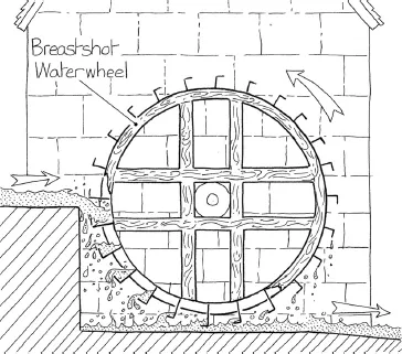
FIG 3.4: Probably the most common arrangement – the breastshot wheel. This depends on either a weir or a long leat taken from well up the stream that feeds it. The power now comes partly from the weight of the water and partly from its speed.
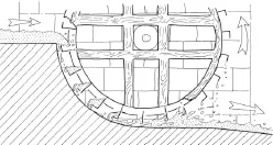
FIG 3.5: A later improvement ran the stonework tight to the curve of the wheel, thus preventing any water from escaping before all its energy had been put into the wheel. Combined with a curved bucket these changes increased the efficiency from around 20% to well over 50%.
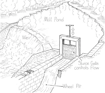
FIG 3.6: This drawing shows the principal parts of a small rural mill pond. There are hundreds of ponds like this on streams around the country even though the mill may have long vanished.
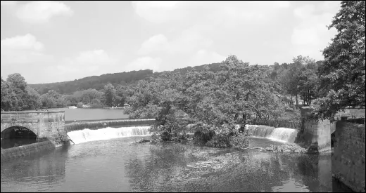
FIG 3.7: Some mill ponds grew to enormous size like this spinning mill weir pond in Belper, Derbyshire, which extends above the weir for over ½ mile up the river Derwent.
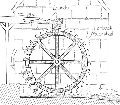
FIG 3.8: The largest diameter wheels were the overshot and pitchback wheels. The overshot wheel lets the water flow naturally onto the wheel top but this turns the wheel in the opposite direction to breastshot or undershot wheels. Quite often these larger diameter wheels were installed to replace a smaller breastshot wheel. This meant all the machinery in the mill would have to change direction. A much cheaper option was to use the pitchback wheel as shown above. This loses a little of the energy but turns the wheel the same way as a breastshot wheel.
Where the river or stream dropped steeply, it was possible to take the leat from greater heights and then tip the water onto the top of the wheel – the overshot wheel. This made maximum use of the weight of the water and allowed a narrower wheel to produce the same energy as a normal-sized breastshot wheel. It usually involved taking the water to the top of the wheel in some form of elevated channel (launder), originally constructed of wood.
One rather special mill was the tidal mill, which had the mill pond filled by the incoming tide and then ran the water back to sea via the waterwheel. Although limited to working in sympathy with the tides, it did have the virtue of not running out of water!
As ironwork improved in the 1700s more and more of the wooden parts were replaced. First joints would be strengthened, particularly around the main shaft, and later the shaft itself would be cast in iron along with the main bearings. The spokes, launders and eventually the whole wheel were produced in iron by the 1800s.
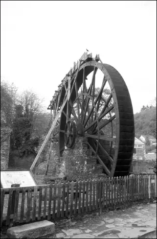
FIG 3.9: At Morwellham Quay in Devon you can see this large diameter overshot wheel, which used to power a manganese grinding mill.
Though we tend to think of the waterwheel producing a rotating motion, some were built to drive pumps using a crank to give a to and fro motion. Often the waterwheel was located a long way from the mines or pits that were being pumped out, and the to and fro motion was transmitted by long runs of stout wooden or iron beams running on rollers between the waterwheel and the pumps. The greatest of these is on the Isle of Man, at Laxey. Built in 1854, with a 72 ft 6 in (22 m) diameter wheel, the pump beams travelled 450 yards (412 m) to the pumps.
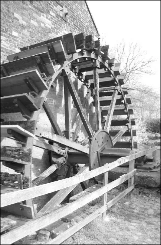
FIG 3.10: This breastshot wheel shows the mix of wood and iron. The shaft is a casting along with the rim but the spokes and paddles are still wood. This mill at Cheddleton near Stoke on Trent is another water-driven mill that was converted from flour grinding to serve early industry. It ground flint for use in the nearby pottery industries.
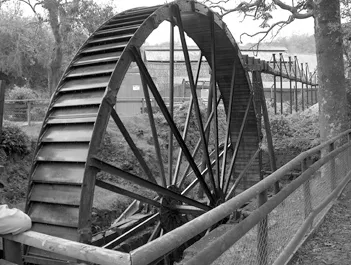
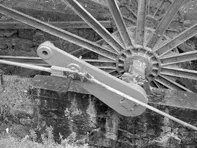
FIG 3.11: This 35 ft (10 m) diameter pitchback wheel turned a crank (right) which drove rods used to pump china clay slurry from the nearby pits at the Wheal Martyn China Clay Museum in Cornwall.
The waterwheel itself would turn far too slowly for the grindstones used in milling so it was normal for the drive to be taken to the grindstones via at least two step-up gears. Made of wood until cast iron took over in the late 1700s, the first gears (pit wheel and wallower) would turn the drive from a horizontal to vertical direction and increase the speed by around three times. This vertical shaft carried the large spur gear which, in turn, drove typically two smaller gears (stone nut) that turned the grinding stones.
Most grinding stones rotated around 150 to 250 times a minute which would seem pretty frightening for anyone standing close by. Right to the end of waterwheel construction, wooden teeth (beech, apple wood or pear wood) were often used for one of the gears to prevent having a metal to metal contact which could produce a spark – the risk of igniting the flour dust was very real. These wooden teeth also kept the noise made by the gears to a low level and, in the event of a major jamming, they would shear off rather than ruin the cast wheels and the shafts.
The need to turn the stones much faster than the wheel rotated was later met by taking the power from the rim of the waterwheel rather than the centre shaft. A strong cast iron gear track would be fitted around the outer edge of the wheel, which drove a smaller gear wheel mounted on a shaft that entered the mill. This rotated much faster than the waterwheel itself and reduced the need to have massive gearing inside the mill.
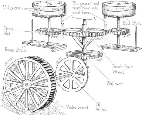
FIG 3.12: The internal workings of a typical waterwheel-driven flour mill. The gearing not only changes the horizontal drive from the wheel to vertical but provides the increase in speed needed for the stones. The tenter board allows the entire top stone and its shaft to be raised or lowered to adjust the gap between the grinding stones. The lower bed stone is always fixed in position and stationary.
This development had another, not so obvious, benefit. When the drive was taken from the centre shaft of a waterwheel, the power had to be taken from the circumference, where the water was falling, and be transmitted to the centre shaft via the spokes. Thus, the spokes were not just holding the wheel in shape but were also carrying the turning forces. This evoked a need for consid...
Table of contents
- Cover Page
- Title Page
- Copyright Page
- Contents
- Introduction
- Section I: A Brief History
- Section II: Stars of the Show
- Section III: The Supporting Cast
- Section IV: Reference
- Index
Frequently asked questions
Yes, you can cancel anytime from the Subscription tab in your account settings on the Perlego website. Your subscription will stay active until the end of your current billing period. Learn how to cancel your subscription
No, books cannot be downloaded as external files, such as PDFs, for use outside of Perlego. However, you can download books within the Perlego app for offline reading on mobile or tablet. Learn how to download books offline
Perlego offers two plans: Essential and Complete
- Essential is ideal for learners and professionals who enjoy exploring a wide range of subjects. Access the Essential Library with 800,000+ trusted titles and best-sellers across business, personal growth, and the humanities. Includes unlimited reading time and Standard Read Aloud voice.
- Complete: Perfect for advanced learners and researchers needing full, unrestricted access. Unlock 1.5M+ books across hundreds of subjects, including academic and specialized titles. The Complete Plan also includes advanced features like Premium Read Aloud and Research Assistant.
We are an online textbook subscription service, where you can get access to an entire online library for less than the price of a single book per month. With over 1.5 million books across 990+ topics, we’ve got you covered! Learn about our mission
Look out for the read-aloud symbol on your next book to see if you can listen to it. The read-aloud tool reads text aloud for you, highlighting the text as it is being read. You can pause it, speed it up and slow it down. Learn more about Read Aloud
Yes! You can use the Perlego app on both iOS and Android devices to read anytime, anywhere — even offline. Perfect for commutes or when you’re on the go.
Please note we cannot support devices running on iOS 13 and Android 7 or earlier. Learn more about using the app
Please note we cannot support devices running on iOS 13 and Android 7 or earlier. Learn more about using the app
Yes, you can access The Industrial Revolution Explained by Stan Yorke in PDF and/or ePUB format, as well as other popular books in History & 19th Century History. We have over 1.5 million books available in our catalogue for you to explore.