![]()
Chapter 1
Introducing the Twin and its Systems
The step up to a twin involves a significant change in complexity from the small single-engine aircraft in which you trained. Probably the best way to approach the twin is to firstly become familiar with the complex single, which has many systems in common with a typical twin. Then we will separately tackle the multi-engine aspects. Let’s start with a brief look at the features of a typical complex single. The most noticeable features will be:
• retractable landing gear;
• electrically operated flaps;
• perhaps electrically operated elevator trim;
• rudder trim in addition to elevator trim;
• constant-speed propeller; and
• turbocharger on the engine.
It could also have the following:
• IFR instrumentation, including an autopilot and, perhaps, weather radar;
• separate entrance for the passengers;
• air conditioning and, perhaps, pressurization;
• oxygen system; or
• several baggage compartments and a more complex loading system.
The principle of operation of these systems is well and truly described in the ASA-PM-2 and -3, Ground School and Instrument Flying manuals, so let’s concentrate on the practical implications and functioning of these systems.
The landing gear will be electrically selected. The normal extension and retraction will either be direct by an electric motor or indirect by an electrically driven hydraulic pump. There is little difference between them as far as the pilot is concerned. The hydraulic gear tends to be faster operating.
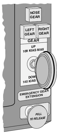
■ Landing gear selector and lights
There will be limiting speeds for operation of the gear (VLO) and for flight with it extended (VLE).There may even be one maximum speed for selecting the gear down and another maximum speed after takeoff by which the landing gear must be up. The Pilot’s Operating Handbook will explain the particular limits for your aircraft.
The lights show green when the gear is down and locked, red when the gear is in transit, and go out when the wheels are up and locked. The gear will have a micro-switch on one leg, known as the squat switch, to prevent up selection when there is weight on the wheels. There will be a warning horn that operates when the throttles are retarded at low airspeed and the gear is up. It may also depend on flap position.
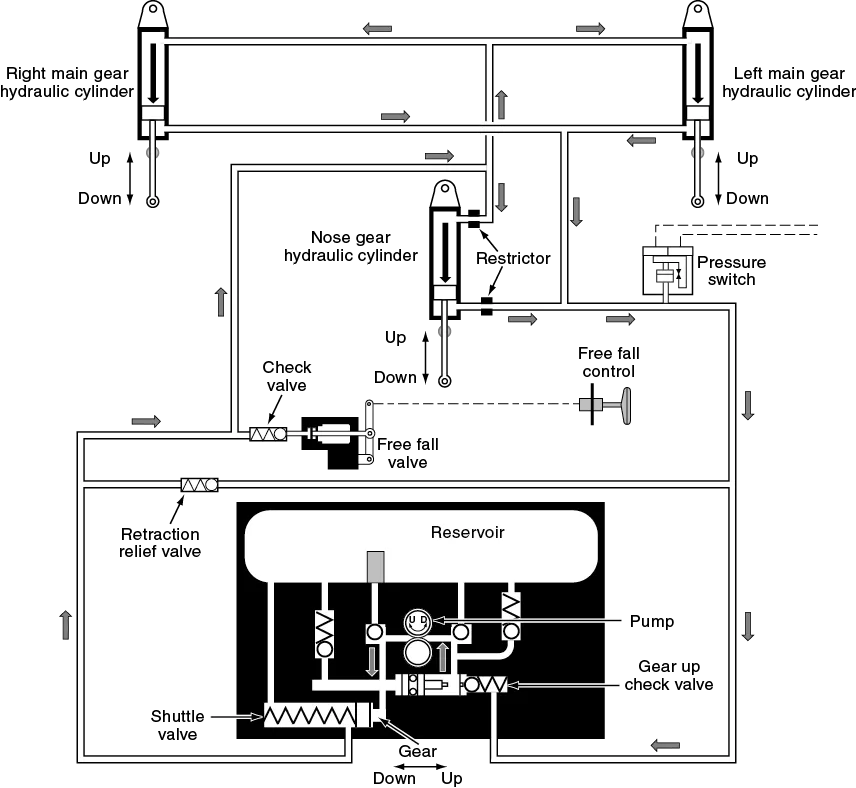
■ Typical hydraulic retractable landing gear system
There will be an emergency extension facility—either:
• a pressure dump and gravity drop of the gear (free fall);
• a manual handle to pump the gear down hydraulically; or
• a crank handle which will manually wind the gear down.
The manual crank may take 50–60 turns and may be difficult to operate while flying. Practice occasionally in VFR conditions.
With manual extension there may be no lights to indicate the landing gear is down and locked—but generally you can feel them extend and lock. (There may be a mirror on the side of the engine nacelle of the twin to visually check the extension of the nosewheel.)
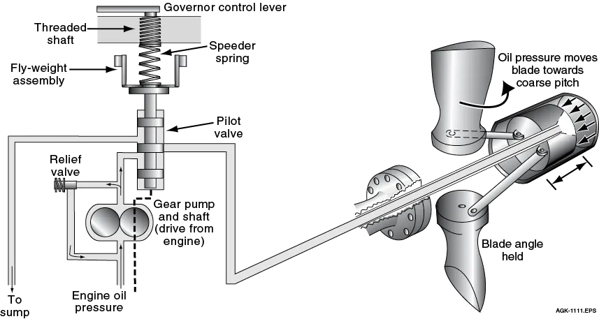
Constant-Speed Propeller
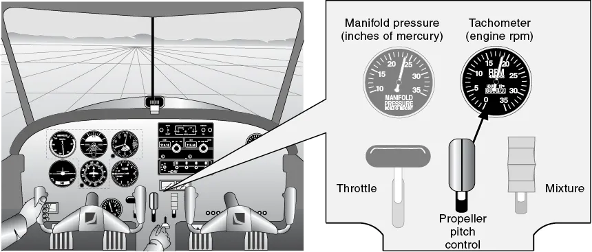
The constant-speed propeller offers a much higher level of efficiency and, with it, some complication in its operation. Oil pressure is used to drive the blade angle, and a governor mechanism then controls the angle to maintain the selected RPM. Loss of oil pressure causes the blades to go to the full fine position. In addition to the RPM indicator, the pilot has a manifold pressure gauge (MP) with units of inches of mercury. Power is set by a combination of MP and RPM. The throttles control MP and the propeller levers, RPM. Typical settings are 25 in./2,500 RPM for climb and 23 in./2,300 RPM for cruise.
To avoid stress on the engine, MP should be less than RPM ÷ 100.
■ Constant speed propeller unit
The levers have to be selected in a certain order (prop up before throttle and throttle back before RPM reduction—revs up and throttle back) to avoid the risk of detonation.
■ Propeller rpm selector from cockpit
Flaps could be manually or electrically operated by a simple switch with detents for up, takeoff and land positions. There is a sensor on the flaps to stop the electric motor when the flaps reach the selected setting (select and forget). There is a position indicator to show the actual position of the flaps. They are mechanically connected to prevent asymmetric positions. It is very valuable to be able to reach and select the various flap positions without having to look inside for the switch or to read the position indicator—except for confirmation. A little time spent in the cockpit rehearsing all checks is worthwhile. (Chuck Yeager learned his checks until he could do them blindfolded.)
Electric Trim
For the electric trim system, the usual cable-operated elevator trim has an electric motor to position both the trim tab and the trim wheel. (It is quite remarkable to watch the trim wheel in a Boeing aircraft spinning under the influence of the electric trim!) The trim switch will be on the contro...