No matter how well equipped your workshop may be, the need to make special tools, devices, and gadgets will always arise. That's where Metalworking for Home Machinists steps in to help! This highly-detailed guide shows you how to create 53 ancillary devices, including 5 clamps and vices, 10 jigs and fixtures, 25 lathe projects, and 13 miscellaneous projects. A must-have resource for every metalworking workshop, this manual will help save you time by devising the needed device for you so you can get right to work building what you need without delaying the completion of your final project any further! Written by an industry expert in designing and building engines and machines, author Tubal Cain had over 60 years of experience, and is a leading voice to guide you through the creation of essential workshop devices.

- 250 pages
- English
- ePUB (mobile friendly)
- Available on iOS & Android
eBook - ePub
About this book
Trusted by 375,005 students
Access to over 1.5 million titles for a fair monthly price.
Study more efficiently using our study tools.
Information
SECTION 1
Getting Hold of the Job
A proper hold of the workpiece is fundamental to all manufacture, whether of models or in full-scale production. But we have a rather special problem as many components are either too small or too thin to grip firmly. We cannot afford either the time or the money to invest in the sophisticated workholding devices used in industry.
In this short section I have not covered the obvious accessories like chucks and bench vises, nor jigs and fixtures which come later. The former are normal workshop equipment and the latter are usually special for each job that crops up. However, I hope that the following pages may save a few workpieces, and perhaps also fingers, from damage. More important, they may suggest to you other ways of tackling those awkward jobs; if so, please don’t keep quiet about them – make sketches, take a photograph and send a note to the editor of Model Engineer (also published by Nexus Special Interests).
The thinpiece vise
The holding of thin material in the vise has always presented problems. The unit described here will overcome most of them for material down to about 32in. thick. It was originally devised as an apprentice training exercise by the supervisor of the training school of a large firm, and has given me excellent service for many years. The design has been simplified for the model engineer’s use, so that the drawings and the photographs do not quite correspond (e.g. items 4 and 5 are milled from a single piece of material in the original). See Fig 1.1.
Make the jaws, items 4 and 7 (Fig. 1.2) first, as these will be required as gages for the top plate and body. The ideal material is 1/2 in. square ground gage stock as this needs no preparation. Failing this, take an 8 1/2in. piece of 1/2 in. material and carefully file parallel and square. Keep the width to a uniform thickness – plus or minus 0.001 in. The depth is not so critical. File one end square, cut off a piece 4 1/16 in. long and repeat the process. (The squared ends will ultimately be the top of the jaws.) Coat with copper sulphate or marking blue and mark out all holes and the slots in the lower ends, taking all dimensions from the squared ends.
Tackle the slots before the rest, so that if this job goes awry as little work as possible is wasted. As an apprentice exercise these are made using hacksaw and file, which is probably quicker than attacking them with a 3/16 in. slot drill, but if a 2 1/2 in. x 3/16 in. slitting saw is available this will make short work of the cut. Run at about 60 rpm and feed the work in steadily, using plenty of cutting oil. Finish off with a 4in. warding file if need be, making the front jaw a tight fit on a 16in. thick gage (e.g. the material for part 5) and the rear jaw a sliding fit. Remove burrs.
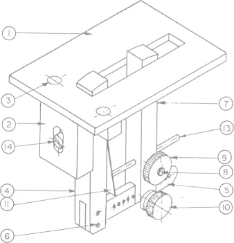
Fig. 1.1 Thinpiece vise.
Drill and tap the holes in the front jaw, but leave the two No. 31 holes at the bottom for the present. The exact shape of the ‘oval’ hole in the rear jaw is unimportant, as part 8 can be made to fit. The quickest way is to drill two 3/16in. holes at a 5/6in. centers and file out the remainder, but professionals will doubtless use patience and a slot drill! Do not drill the a 5/32in. cross hole yet. Drill No. 37 as shown, open out one side to 1/8in. and tap the other side 5BA using the 1/8in. hole as a guide.
Now hold the jaws side by side in the vise – making sure they are the right way round – and file the previously squared ends to the 2 in. radius shown. The bottom end of the rear jaw may now be radiused, but leave the front jaw for the present.
The top plate, item 1, is best made from ground flat stock, but mild steel plate will serve if it is truly flat. File to shape and mark out the slot and the two rivet holes, taking care that the 5/32in. dimension is reasonably accurate. Drill a series of 3/16in. holes (1,000 rpm if ground stock, 2,000 rpm if BMS for HSS drills) well inside the lines of the slot and file until the jaws are a nice sliding fit. See that the ends of the slot are square. Start the rivet holes with a Slocombe drill, but do not drill through.
The body, item 2, calls for some energetic work with hacksaw and file to bring to the T shape. It is important that the top face be flat, and square to the front face with the 1/2in. groove in it. Mark out the front face for this groove, set up on the vertical slide with a piece of packing behind, so that the groove may be milled using the saddle cross slide, and make sure (a) that the 2 3/8in. wide top face is square to the lathe bed and (b) that the front face is square across the bed. Using a 3/8in. slot drill at about 650 rpm take a full depth cut across the center of the slot and then work carefully toward the two lines with light cuts until the front jaw is a nice sliding fit in the groove.
Now adjust the vertical slide until the center of the groove is at exact center height, and with a Slocombe drill in the chuck start a hole 9/16in. from the top face. Follow this with a 3/16in. drill to make a hole right through (hence the need for packing behind). Chuck a 3/16in. slot drill and cut the 3/16in. slot as shown, slightly deeper than the drawing requires. Remove the work, and transfer the center of the slot to the other side of the body. Set up on the vertical slide, squaring up as before; line up with the 3/16in. hole. Drill a 3/8in. hole on the center until it just breaks into the 3/16in. slot and follow with a 3/8 in. slot drill to machine the slotted counterbore (if your drills have a tendency to run oversize holes, use a No. 14 and letter U instead of 3/16in. and 3/8in.).
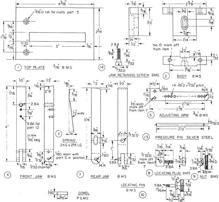
Fig. 1.2 Details of thinpiece vise.
Use plenty of cutting oil during the milling operations, and keep a steady feed allowing no rubbing without cutting.
The adjusting arm, part 5, is a simple filing and drilling job, best made of ground flat stock, but BMS flat will do. The row of holes can be drilled very accurately by mounting the arm (with packing behind) on the vertical slide. With a Slocombe drill in the chuck, deeply drill the first hole; advance the cross slide 156 thou, drill the next, and so on. The holes may then be finished to 1/8 in. in the drilling machine, but the pitch and alignment will be really true. Lightly countersink both sides. Do not drill the two No. 31 holes yet.
The two rivets, item 3, are turned from soft mild steel or from a longer 5/16in. iron rivet. The dowels, item 6, are parted off from ground BMS rod, not drill rod, and the pressure-pin, item 13, from drill rod. The locking plug, item 8, is made by chucking a piece of 3/16in. x 1/2in. steel in the 4-jaw, turning the screwed part 0.160/0.161 in. dia. and screwing 3 BA with the tailstock dieholder. The rectangular plug is then filed a nice fit into the hole in the rear jaw. Assemble into the jaw with the faces A’ flush, and drill in. right through. (Purists may prefer to drill No. 24 and ream, but this is not necessary.) Lightly countersink the entrances to the holes.
The nut and pin, items 9 and 10, are simple turning jobs, the exact shape of the heads being left to individual taste but knurl before parting off in both cases. The screw, No. 14, may be a standard Allen socket-head, if desired.
It should be possible to put the kink in the spring, item 11, without softening it, if held in the smooth jaws of the vise. If the holes are to be drilled, run no faster than 360 rpm, hone the drill point so that it is really sharp; rest the workpiece on a piece of steel packing and on no account hold the spring in the hand while drilling. It may be simpler to punch the holes with a sharp flat punch on a lead anvil.
Attach the front jaw 4 to the body 2 with a piece of paper (or .002 in. shim) in the bottom of the groove, using the screw 2. Clamp the top 1 to the body, ensuring that the jaw is hard up against the end of the slot. Drill and ream the two 3/16in. fixing holes. Dismantle and countersink the holes as shown and remove burrs. Insert the rivets 3, rivet up and carefully file flush. File the end of the slot in the top plate so that it is flush with the groove. It may be necessary to ease the slot a trifle to ensure that the jaw can slide up and down.
Insert the arm 5 into the slot in the jaw 4, first smearing some Easyflo paste flux on the mating parts. Check that it is square to the jaw. Drill and ream the upper hole; press in one of the dowels 6 and rivet lightly. Check for squareness, drill and ream the second hole and fit the pin as before. Heat to dull red, apply Easyflo silver solder, allow to cool to black, and quench in cold water.
File the lower end of the jaw to the profile of the arm, and smooth off the projecting pins. Polish off with fine emery. Attach the spring. Push the plug 8 into its place in the jaw 7, insert the pin 13 and lightly tighten the nut 9. Assemble the jaw to the arm 5 with the pin 10. The whole jaw assembly is attached to the body by the screws 14.
In service, the unit is held in the bench vise (with fiber grips in place) with the jaw 4 to the front, Fig 1.3. The projection of the jaws is adjusted by means of the screw 14 to suit the thickness of the job to be held. The rear jaw position is adjusted on the arm to suit the width of the workpiece, and the pressure pin positioned so that the spring opens the jaws to follow those of the bench vise.
My own vise has been in fairly constant use for 25 years. It would pay to harden the ends of the moving jaws. This can be done by casehardening; heat up to red and cover the top half-inch with Kasenit compound. Reheat to red again (see the instructions on the tin) and quench in water. There is no need to get the whole of the arm hot, of course. This operation should be done before uniting parts 4 and 5. After cleaning up and polishing this joining can be done but, while brazing, immerse the lower ends (that is, the hard tops) in a water bath. This will prevent drawing the hardness of the nose of the jaws.
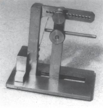
Fig. 1.3 An underside view of the vise.
Although the top plate has got a little scarred with use I doubt if it is worth hardening this, although if gage plate is used it can be done by heating to about 800°C for say ten minutes (cherry red) and then quenching in oil, vertically. Temper to pale straw. The risk is that the plate may distort, and there is the added point that a hard plate will damage the files. My own is soft gage plate and the way things are going I may have to make a new top in ten or a dozen years’ time; cheaper than new files!
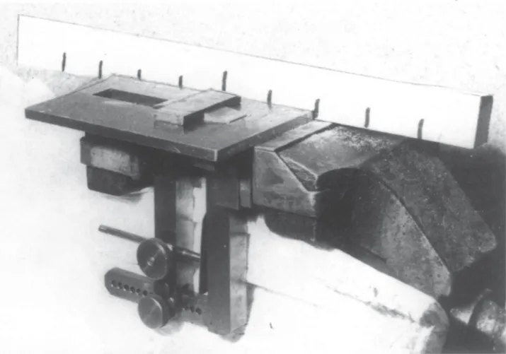
Fig. 1.4 In service – though the workpiece is rather thick!
Circular work in the drilling vise
All the books tell you that work should be clamped to the table or held in a vise while drilling, and this applies especially when working in brass or gunmetal. The material drags at the drill point and unless you have the old-fashioned straight flute drills (or the modern, and expensive, slow helix type) a ‘snatch’ when breaking through is inevitable. (You ought, of course, to take off the rake at the drill point when drilling brass and then resharpen for normal work, which means that after 12 months or so all your drills will be tiny stubs of HSS!.) So, drilling vise or clamp it must be. The snag comes when holding small round objects; stuffing box glands, for example. Even if your vise is furnished with vees on the jaw faces there is the risk of marking the carefully turned stem of the gland and if you don’t grip hard enough the drill will pull the job out of the vise and do more damage still; to you or to the job!
Fig. 1.5 shows how I got over this problem. The block is made from a piece of close-grained hardwood. Do not use oak – beech should do, and yew better still. But I use lignum vitae, which can be obtained from worn-out bowls woods or old foundry rammers. A good alternative is b...
Table of contents
- Cover
- Title
- Copyrights
- Contents
- Introduction
- Section 1: Getting Hold of the Job
- Section 2: Jigs and Fixtures
- Section 3: Round and About the Lathe
- Section 4: Miscellaneous
Frequently asked questions
Yes, you can cancel anytime from the Subscription tab in your account settings on the Perlego website. Your subscription will stay active until the end of your current billing period. Learn how to cancel your subscription
No, books cannot be downloaded as external files, such as PDFs, for use outside of Perlego. However, you can download books within the Perlego app for offline reading on mobile or tablet. Learn how to download books offline
Perlego offers two plans: Essential and Complete
- Essential is ideal for learners and professionals who enjoy exploring a wide range of subjects. Access the Essential Library with 800,000+ trusted titles and best-sellers across business, personal growth, and the humanities. Includes unlimited reading time and Standard Read Aloud voice.
- Complete: Perfect for advanced learners and researchers needing full, unrestricted access. Unlock 1.5M+ books across hundreds of subjects, including academic and specialized titles. The Complete Plan also includes advanced features like Premium Read Aloud and Research Assistant.
We are an online textbook subscription service, where you can get access to an entire online library for less than the price of a single book per month. With over 1.5 million books across 990+ topics, we’ve got you covered! Learn about our mission
Look out for the read-aloud symbol on your next book to see if you can listen to it. The read-aloud tool reads text aloud for you, highlighting the text as it is being read. You can pause it, speed it up and slow it down. Learn more about Read Aloud
Yes! You can use the Perlego app on both iOS and Android devices to read anytime, anywhere — even offline. Perfect for commutes or when you’re on the go.
Please note we cannot support devices running on iOS 13 and Android 7 or earlier. Learn more about using the app
Please note we cannot support devices running on iOS 13 and Android 7 or earlier. Learn more about using the app
Yes, you can access Metalworking for Home Machinists by Tubal Cain in PDF and/or ePUB format, as well as other popular books in Technology & Engineering & Mining Engineering. We have over 1.5 million books available in our catalogue for you to explore.