High Performance Control of AC Drives with Matlab®/Simulink
Explore this indispensable update to a popular graduate text on electric drive techniques and the latest converters used in industry
The Second Edition of High Performance Control of AC Drives with Matlab®/Simulink delivers an updated and thorough overview of topics central to the understanding of AC motor drive systems. The book includes new material on medium voltage drives, covering state-of-the-art technologies and challenges in the industrial drive system, as well as their components, and control, current source inverter-based drives, PWM techniques for multilevel inverters, and low switching frequency modulation for voltage source inverters.
This book covers three-phase and multiphase (more than three-phase) motor drives including their control and practical problems faced in the field (e.g., adding LC filters in the output of a feeding converter), are considered.
The new edition contains links to Matlab®/Simulink models and PowerPoint slides ideal for teaching and understanding the material contained within the book. Readers will also benefit from the inclusion of:
A thorough introduction to high performance drives, including the challenges and requirements for electric drives and medium voltage industrial applications
An exploration of mathematical and simulation models of AC machines, including DC motors and squirrel cage induction motors
A treatment of pulse width modulation of power electronic DC-AC converter, including the classification of PWM schemes for voltage source and current source inverters
Examinations of harmonic injection PWM and field-oriented control of AC machines
Voltage source and current source inverter-fed drives and their control
Modelling and control of multiphase motor drive system
Supported with a companion website hosting online resources.
Perfect for senior undergraduate, MSc and PhD students in power electronics and electric drives, High Performance Control of AC Drives with Matlab®/Simulink will also earn a place in the libraries of researchers working in the field of AC motor drives and power electronics engineers in industry.
Trusted by 375,005 students
Access to over 1.5 million titles for a fair monthly price.
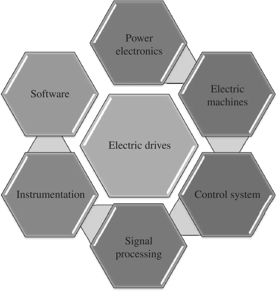
The function of an electric drives system is the controlled conversion of electrical energy to a mechanical form, and vice versa, via a magnetic field. Electric drive is a multidisciplinary field of study, requiring proper integration of knowledge of electrical machines, actuators, power electronic converters, sensors and instrumentation, control hardware and software, and communication links (Figure 1.1). There have been continued developments in the field of electric drives since the inception of the first principle of electrical motors by Michael Faraday in 1821 [1]. The world dramatically changed after the first induction machine was patented (US Patent 381968) by Nikola Tesla in 1888 [2]. Initial research focused on machine design with the aim of reducing the weight per unit power and increasing the efficiency of the motor. Constant efforts by researchers have led to the development of energy‐efficient industrial motors with reduced volume machines. The market is saturated with motors reaching high efficiency of almost 95–96%, resulting in no more significant complaints from users [3]. AC motors are broadly classified into three groups: synchronous, asynchronous (induction), and electronically commutated motors. Asynchronous motors are induction motors with a field wound circuit or with squirrel cage rotors. Synchronous motors run at synchronous speeds decided by the supply frequency (Ns = 120f/P) and are classified into three major types: rotor excited, permanent magnets, and synchronous reluctance types. Electronic commutated machines use the principle of DC machines but replace the mechanical commutator with inverter‐based commutations. There are two main types of motors that are classified under this category: brushless DC motors and switched reluctance motors. There are several other variations of these basic configurations of electric machines used for specific applications, such as stepper motors, hysteresis motors, permanent magnet‐assisted synchronous reluctance motors, hysteresis‐reluctance motors, universal motors, claw pole motors, frictionless active bearing‐based motors, linear induction motors, etc. Active magnetic bearing systems work on the principle of magnetic levitation and, therefore, do not require working fluid, such as grease or lubricating oils. This feature is highly desirable in special applications, such as artificial heart or blood pumps, as well as in the oil and gas industry.
Figure 1.1 Electric drive system
Induction motors are called the workhorse of industry due to their widespread use in industrial drives. They are the most rugged and cheap motors available off the shelf. However, their dominance is challenged by permanent magnet synchronous motors (PMSM), because of their high power density and high efficiency due to reduced rotor losses. Nevertheless, the use of PMSMs is still restricted to the high‐performance application area, due to their moderate ratings and high cost. PMSMs were developed after the invention of Alnico, a permanent magnet material, in 1930. The desirable characteristics of permanent magnets are their large coercive force and high reminiscence. The former characteristics prevent demagnetization during start and short conditions of motors, and the latter maximizes the air gap flux density. The most used permanent magnet material is neodymium–boron–iron (NdBFe), which has almost 50 times higher B‐H energy compared to Alnico. The major shortcomings of permanent magnet machines are the nonadjustable flux, irreversible demagnetization, and expensive rare‐earth magnet resources. Variable flux permanent magnet (VFPM) machines have been developed to incorporate the adjustable flux feature. This variable flux feature offers flexibility by optimizing efficiency over the whole machine operation range, enhancing torque at low speed, extending the high speed operating range, and reducing the likelihood of an excessively high back‐electromotive force (EMF) being induced at high speed during inverter fault conditions. The VFPMs are broadly classified into hybrid‐excited machines (they have the field coils and the permanent magnets) and mechanically adjusted permanent magnet machines. Detailed reviews on the variable flux machines are given in [4]. The detailed reviews on the advances on electric motors are presented in [5–16].
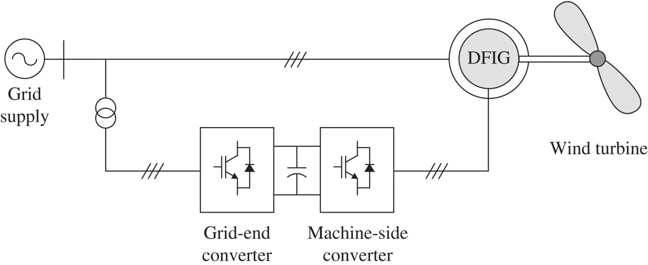
Figure 1.2 General view of a DFIG connected to wind system and utility grid
Another popular class of electrical machine is the double‐fed induction machine (DFIM) with a wound rotor. The DFIM is frequently used as an induction generator in wind energy systems. The double‐fed induction generator (DFIG) is a rotor‐wound, three‐phase induction machine that is connected to the AC supply from both stator and rotor terminals (Figure 1.2). The stator windings of the machine are connected to the utility grid without using power converters, and the rotor windings are fed by an active front‐end converter. Alternatively, the machine can be fed by current or voltage source inverters with controlled voltage magnitude and frequency [17–22].
In the control schemes of DFIM, two output variables on the stator side are generally defined. These variables could be electromagnetic torque and reactive power, active and reactive power, or voltage and frequency, with each pair of variables being controlled by different structures.
The machine is popular and widely adopted for high‐power wind generation systems and other types of generators with similar variable‐speed high‐power sources (e.g. hydro systems). The advantage of using this type of machine is that the required converter capacity is up to three times lower than those that connect the converter to the stator side. Hence, the costs and losses in the conversion system are drastically reduced [17].
A DFIG can be used either in an autonomous generation system (stand‐alone) or, more commonly, in parallel with the grid. If the machine is working autonomously, the stator voltage and frequency are selected as the controlled signals. However, when the machine is connected to the infinite bus, the stator voltage and frequency are dictated by the grid system. In the grid‐interactive system, the controlled variables are the active and reactive powers [23–25]. Indeed, there are different types of control strategies for this type of machine; however, the most widely used is vector control, which has different orientation frames similar to the squirrel cage induction motor; however, the most popular of these is the stator orientation scheme.
Power electronics converters are used as an interface between the stiff voltage and frequency grid system and the electric motors to provide adjustable voltage and frequency. This is the most vital part of a drive system that provides operational flexibility. The development in power electronic switches is steady, and nowadays high‐frequency low‐loss power semiconductor devices are available for manufacturing efficient power electronic converters. The power electronic converter can be used as DC‐DC (buck, buck–boost, boost converters), AC‐DC (rectifiers), DC‐AC (inverters), and AC‐AC (cycloconverters and matrix converters) modes. In AC drive systems, inverters are used with two‐level output or multilevel output (particularly for higher‐power applications). The input side of the inverter system can consist of a diode‐based, uncontrolled rectifier or controlled rectifier for regeneration capability called back‐to‐back or active front‐end converter. The conventional two‐level inverter has the disadvantages of the poor source‐side (grid‐side) power factor and distorted source current. The situation is improved by using back‐to‐back converters or matrix converters in drive systems.
The output‐side (AC) voltage/current waveforms are improved by employing the appropriate pulse width modulation (PWM) technique, in addition to using a multilevel inverter system. In modern motor drives, the transistor‐based [insulated gate bipolar transistor (IGBT), integrated gate‐commutated thyristor (IGCT), MOSFET] converters are most commonly used. The increase in transistors switching frequency and decrease in transistor switching times are a source of some serious problems. The high dv/dt and the common‐mode (CM) voltage generated by the inverter PWM control result in undesirable bearing currents, shaft voltages, motor terminal overvoltages, reduced motor efficiency, acoustic noise, and electromagnetic interference (EMI) problems, which are aggravated by the long length of the cable between the converter and the motor. To alleviate such problems, generally, the passive LC filters are installed on the converter output. However, the use of an LC filter introduces unwanted voltage drops and causes a phase shift between the filter input and output voltages and currents. These can negatively influence the operation of the whole drive system, especially when sophisticated speed, sensorless control methods are employed, requiring some estimation and control modifications for an electric drive system with an LC filter at its output. With the LC filter, the principal problem is that the motor input voltages and currents are not precisely known; hence, additional voltage and current sensors are employed. Since the filter is an external element of the converter, the requirement of additional voltage and current sensors poses technical and economical problems in converter design. The more affordable solution is to develop proper motor control and use estimation techniques in conjunction with LC filter‐based drive [26–30].
The simulation tool is a significant step for performing advanced control for industry. However, for practical implementation, the control platform for the electric drive system is provided with microcontrollers (mCs), digital signal processors (DSPs), and/or field‐programmable gate arrays (FPGAs). These control platforms offer the flexibility of control and make possib...
Table of contents
Cover
Table of Contents
Title Page
Copyright Page
Dedication Page
Acknowledgment
Biographies
Preface to Second Edition
Preface to First Edition
About the Companion Website
1 Introduction to High‐Performance Drives
2 Mathematical and Simulation Models of AC Machines
3 Pulse‐Width Modulation of Power Electronic DC–AC Converter
4 Field‐Oriented Control of AC Machines
5 Direct Torque Control of AC Machines
6 Nonlinear Control of Electrical Machines Using Nonlinear Feedback
7 Five‐Phase Induction Motor Drive System
8 Sensorless Speed Control of AC Machines
9 Selected Problems of Induction Motor Drives with Voltage Inverter and Inverter Output Filters
10 Medium Voltage Drives – Challenges and Trends
11 Current Source Inverter Fed Drive
Index
End User License Agreement
Frequently asked questions
Yes, you can cancel anytime from the Subscription tab in your account settings on the Perlego website. Your subscription will stay active until the end of your current billing period. Learn how to cancel your subscription
No, books cannot be downloaded as external files, such as PDFs, for use outside of Perlego. However, you can download books within the Perlego app for offline reading on mobile or tablet. Learn how to download books offline
Perlego offers two plans: Essential and Complete
Essential is ideal for learners and professionals who enjoy exploring a wide range of subjects. Access the Essential Library with 800,000+ trusted titles and best-sellers across business, personal growth, and the humanities. Includes unlimited reading time and Standard Read Aloud voice.
Complete: Perfect for advanced learners and researchers needing full, unrestricted access. Unlock 1.5M+ books across hundreds of subjects, including academic and specialized titles. The Complete Plan also includes advanced features like Premium Read Aloud and Research Assistant.
Both plans are available with monthly, semester, or annual billing cycles.
We are an online textbook subscription service, where you can get access to an entire online library for less than the price of a single book per month. With over 1.5 million books across 990+ topics, we’ve got you covered! Learn about our mission
Look out for the read-aloud symbol on your next book to see if you can listen to it. The read-aloud tool reads text aloud for you, highlighting the text as it is being read. You can pause it, speed it up and slow it down. Learn more about Read Aloud
Yes! You can use the Perlego app on both iOS and Android devices to read anytime, anywhere — even offline. Perfect for commutes or when you’re on the go. Please note we cannot support devices running on iOS 13 and Android 7 or earlier. Learn more about using the app
Yes, you can access High Performance Control of AC Drives with Matlab/Simulink by Haitham Abu-Rub,Atif Iqbal,Jaroslaw Guzinski in PDF and/or ePUB format, as well as other popular books in Biological Sciences & System Theory. We have over 1.5 million books available in our catalogue for you to explore.