- 408 pages
- English
- ePUB (mobile friendly)
- Available on iOS & Android
eBook - ePub
Solving Mechanical Design Problems with Computer Graphics
About this book
This book acquaints the reader with interactive computer graphics and how they are being used in the analysis of mechanical design problems. It covers four mechanical design topics: the graphics model, mass properties, stress and strain, and kinematic and kinetic analysis.
Trusted by 375,005 students
Access to over 1.5 million titles for a fair monthly price.
Study more efficiently using our study tools.
Information
1
Introduction
1.1 THE MEANING OF MECHANICAL DESIGN
Engineering is one of the most important of all human activities. The pyramids of Egypt and the aqueducts of ancient Rome were early engineering accomplishments. Engineering produced the steam engine and the machines it powered, which allowed the average person to have some of the things that had previously been available only to the rich. It was engineering that achieved the airplane, fulfilling one of man’s oldest dreams. It is engineering that has made it possible for us to go to the moon. Engineering has the responsibility of providing us with those things that make our lives easier and more interesting.
Design is a creative activity, and it is not an exaggeration to say that our creative efforts have produced those things that most distinguish us from other forms of life. Creativity as it applies to engineering is the ability to conceive basic innovations, to perceive those problems that can readily be solved, to devise solutions to new problems, and to combine familiar concepts in unusual ways. Thus design is the creative part of engineering. The word design will hereafter be used for this aspect of engineering and designer for a person who engages in this activity.
The end result of the design process will hereafter be called the product. Many features desired in a product are incompatible; thus it is readily apparent that design involves making decisions and comprises based on careful consideration of many factors. It also becomes apparent that the designer must continuously exercise judgment and that faulty judgment in only one instance could invalidate an entire design concept.
Design is a large field and it is becoming larger very rapidly as discoveries are made, as inventions are produced, and as new needs arise. These inventions or discoveries do not benefit us directly; it is only when they serve as the basis for a design or are incorporated into a design that we derive a benefit from them. It is also appropriate to point out that a new design is itself of no real significance unless it clearly fulfills a need and is produced in an appropriate quantity.
A designer is concerned with such problems as the geometric arrangement of components, the effect that the motion of one part has on the motions of those associated with it, and the effects of forces. Designers are also concerned with the properties of materials, with the capabilities and limitations of manufacturing processes, with human capabilities and limitations, and with economic matters. Designers must also possess a highly developed ability to present their ideas concerning complex engineering problems in such a manner that they are readily and clearly understood by other technical personnel.
Mechanical design is the application of many of the principles of science and technology in the creation of a product and the consideration of the various factors that affect its production and use.
An understanding of the relation of drafting to design is important to an appreciation of the position of design. Drafting is the preparation of drawings that serve as the means by which the engineering department exactly describes the various parts and assemblies that make up a product, and this requires some ability in graphic science. A designer also makes considerable use of graphic science, which is most conveniently done at a drafting table and/or through a computer graphics system. But to say that the work of designers is drafting would be the same as saying that the work of an author who uses a typewriter is merely typing.
1.2 WHAT ARE INTERACTIVE COMPUTER GRAPHICS?
A new era of enhanced creativity and productivity is possible with the application of computer graphics to the areas of mechanical drafting, design, and engineering. Interactive computer graphics is a partnership between the computer and the human being, combining the best abilities of each to form a powerful drafting, design, and engineering team. This interaction between people and computers is accomplished through the use of cathode-ray-tube (CRT) displays, alphanumeric keyboards, digitizing tablets and pens, and special computer languages.
A person is able to communicate or interact with the computer and receive a direct response from it. This two-way conversation may be graphical or pictorial in nature, with the response time being only seconds. For example, the designer/engineer may generate a picture on the cathode-ray display tube by using a digitizing table and a pen. Due to previous programming, the computer understands the picture, makes calculations based on it, and presents answers or a revised picture to the designer/engineer within a few seconds. The process can be repeated, simulating the same process that is performed on a conventional drafting board, but at a faster rate.
Most interactive computer graphics systems (ICGS) provide the same capabilities as the drawing instruments used by the drafter, designer, or engineer, so that the user can construct a drawing on a CRT display in a manner similar to that used to draw on a drafting board.
A part is drawn on a ICGS by using a graphical vocabulary for constructing points, lines, circles, arcs, and so on. The operator can call up the graphical vocabulary by use of a menu or by means of a pushbutton panel which enables the operator to use the following graphical constructions. The following graphical constructions represent only a small portion of the constructions that are available on most interactive computer graphics systems.
A point may be placed by using any of these options:
- Locating the point by means of a digitizing pen and a tracking cross
- Inputting the coordinates via the keyboard
- Designating the intersection of lines and/or arcs
A line may be drawn by using any of these options:
- Drawing it between two existing points
- Locating the line’s endpoints via the digitizing pen
- Inputting the coordinates of the line’s endpoints via the keyboard
- Drawing it through a point, tangent to a circle
- Drawing it parallel to an existing line at a specified distance from it
- Drawing it through a point at a specified angle to an existing line
- Drawing it tangent to two circles
A circle may be drawn by using any of these options:
- Drawing it with a specified center and radius
- Drawing it with a specified center, tangent to a line
- Drawing it with a specified center, tangent to another circle
A circular arc may be drawn by using any of these options:
- Drawing it tangent to two lines, with a specified radius
- Drawing it tangent to a line and an arc, with a specified radius
- Drawing it tangent to two arcs, with a specified radius
In these constructions, the digitizing pen is used to select points, lines, and circles as required. In addition to being able to use the basic construction features, operators can change the scale and center of the picture at will, establish whatever local coordinate systems they wish, and erase selected elements.
Interactive computer graphics enables the designer/engineer to draw a three-dimensional mathematical model of an object in space. All points, lines, and planes making up this model are defined mathematically in space. Therefore, the designer/engineer has a powerful tool available for calculating distances, angles, lengths, areas, volumes, and so on, of geometric elements in space with extreme quickness and accuracy. Points, lines, and planes making up the object can be manipulated (rotated, moved, copied, stretched, etc.) and stored in files with ease using interactive computer graphics. If the design needs to be altered or improved for any reason, the time for carrying out this redesign is minimal on a interactive computer graphics system. The more design cycles that can be carried out within the limitations of time or budget, the better the results.
The benefits of a interactive computer graphics system can be summarized as follows:
- The user can quickly see and correct any mistakes on a drawing.
- A three-dimensional view can be constructed and shown on the ICG’s CRT display. This three-dimensional view is a spatial model and is beneficial to the designer or engineer during the design process and for engineering analysis work.
- Repetitive tasks can be preprogrammed as part of the computers software. The computer performs the monotonous tasks, so that the operator can spend more time in creative design and problem solving.
- The data generated by a interactive computer graphics system can be used easily by other computers. This feature is very important when it comes to analysis, manufacturing, robotics, forecasting, marketing, scheduling, and so on.
Attempting to explain how the human element works, in the same terms as those used for electromechanical devices, is a challenge to medical science. Identifying what the human being does in an ICGS is a little easier. First, the person has an idea of how to solve the geometry-related problem before beginning to work on the ICGS. These ideas can be in the form of sketches, drawings, and/or in conceptual form in one’s mind. This idea must be entered in the ICGS as a three-dimensional object as it would appear in the real world. This object, known as a three-dimensional graphics model, is defined mathematically in space by points, lines, and planes.
On this graphics model, one can perform various problem-solving solutions, depending on one’s needs. For example, one could generate information concerning how the object could be manufactured or how it would function under actual working conditions. Therefore, the three-dimensional graphics model becomes the explicit data base, comparable to an engineering drawing.
This book is concerned only with the analysis of an object as related to mechanical design. Figure 1.1 illustrates what happens after the graphics model is generated on an ICGS. This process will be referred to as the interactive computer graphics analysis process.
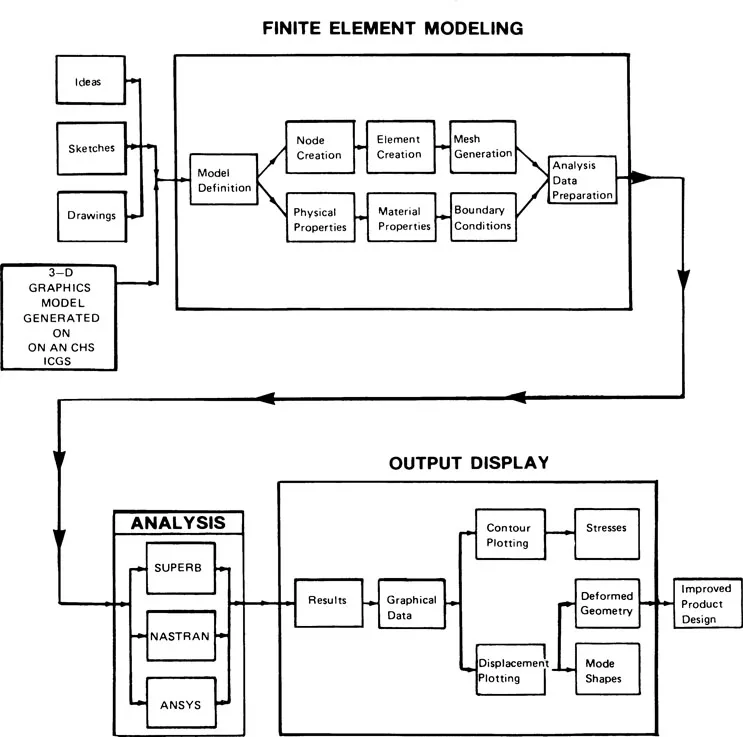
FIGURE 1.1 Interactive computer graphics analysis process.
The steps that are followed in the mechanical design analysis of a three-dimensional graphics model (object) on an ICGS are as follows:
- The model is generated on an ICGS.
- The model is prepared for finite element modeling (commonly known as postprocessing).
- After the model is prepared (model definition), the various nodes, elements, and mesh generation are inputted graphically using the ICGS. This results in a finite element model of the graphics model. Also, the various physical and material properties and boundary ...
Table of contents
- Cover
- Half Title
- Series Page
- Title Page
- Copyright Page
- Preface
- Contents
- 1 Introduction
- 2 Creating the Graphics Model
- 3 Mass Properties
- 4 Stress and Strain
- 5 Design of Mechanisms and Machinery
- Bibliography
- Index
Frequently asked questions
Yes, you can cancel anytime from the Subscription tab in your account settings on the Perlego website. Your subscription will stay active until the end of your current billing period. Learn how to cancel your subscription
No, books cannot be downloaded as external files, such as PDFs, for use outside of Perlego. However, you can download books within the Perlego app for offline reading on mobile or tablet. Learn how to download books offline
Perlego offers two plans: Essential and Complete
- Essential is ideal for learners and professionals who enjoy exploring a wide range of subjects. Access the Essential Library with 800,000+ trusted titles and best-sellers across business, personal growth, and the humanities. Includes unlimited reading time and Standard Read Aloud voice.
- Complete: Perfect for advanced learners and researchers needing full, unrestricted access. Unlock 1.5M+ books across hundreds of subjects, including academic and specialized titles. The Complete Plan also includes advanced features like Premium Read Aloud and Research Assistant.
We are an online textbook subscription service, where you can get access to an entire online library for less than the price of a single book per month. With over 1.5 million books across 990+ topics, we’ve got you covered! Learn about our mission
Look out for the read-aloud symbol on your next book to see if you can listen to it. The read-aloud tool reads text aloud for you, highlighting the text as it is being read. You can pause it, speed it up and slow it down. Learn more about Read Aloud
Yes! You can use the Perlego app on both iOS and Android devices to read anytime, anywhere — even offline. Perfect for commutes or when you’re on the go.
Please note we cannot support devices running on iOS 13 and Android 7 or earlier. Learn more about using the app
Please note we cannot support devices running on iOS 13 and Android 7 or earlier. Learn more about using the app
Yes, you can access Solving Mechanical Design Problems with Computer Graphics by Jerome Lange in PDF and/or ePUB format, as well as other popular books in Technology & Engineering & Computer Graphics. We have over 1.5 million books available in our catalogue for you to explore.