The history of Admiral Horatio Nelson has been written from every possible angle, but this was not so with his ships. Not until this work was first published in 1955. Before then, such information as there was about the ships was buried in archives on Naval Architecture; only the top expert could have sifted it and present it in a usable form.
Dr. Longridge was that expert, and his work became a veritable treasure trove for every naval historian and ship modeller.
His research is supported by 271 detailed line drawings, rare photographs and fold-out plans showing hull framing, interior construction, complexing and deck layouts.

- 313 pages
- English
- ePUB (mobile friendly)
- Available on iOS & Android
eBook - ePub
The Anatomy of Nelson's Ships
About this book
Trusted by 375,005 students
Access to over 1.5 million titles for a fair monthly price.
Study more efficiently using our study tools.
Information
Subtopic
British HistoryIndex
HistoryPART I — THE HULL
CHAPTER I — Construction of Ships of the Period
“Building slipway. Laying of keel. Hogging and sagging. The stern post. The deadwood. Rise of floor. The stem, apron and stemson. Beakhead. The knight heads. The wing transom, horning of. Moulding of frames. Arrangement of floors and futtocks. Ribbands. Cant frames. Harpins. Keelson. Limbers. Breast hooks. Framing of decks. Deck beams, cartings and ledges. Knees. Stern timbers. Counters. Bolts.”
THIS chapter is not concerned with model building, but has been written with the object of giving the reader a bird’s eye view of the main features of a ship, and of its construction, so that he may become familiar with the problems he has to face in building his model.
The building slip was prepared with a series of massive timber blocks, placed about 5 ft. apart, and set with a declivity to the water of from ¾ in. to I in. per foot in length. On the top of each block a cap of straight-grained oak was secured with the grain running parallel with the long axis of the slipway. The ship was built on top of these blocks which had to carry the greater part of its weight. The blocks were about 5 ft. high to allow the men to work under the ship. When the bottom was finished, props or “shores” were fitted underneath to spread the weight and to take some of it off the blocks. (See Plates 33-35 and 38).
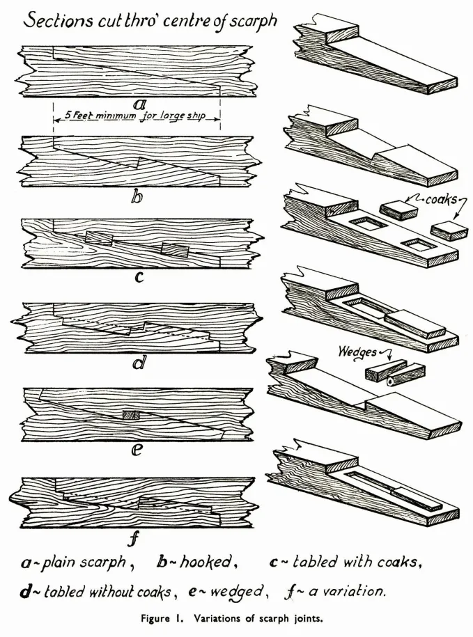
The keel was laid upon these blocks; it was made of English elm, a timber which will stand constant immersion in salt water very well and could be obtained in long straight lengths, but not, however, sufficiently long for one piece to make the keel of a first-rate. Pieces were therefore joined together by means of a joint called a scarph. In the course of his researches while preparing the drawings for this book Mr. Bowness made the interesting and important discovery that the scarphs in the keel were frequently made in the vertical plane, while those in the keelson were made in the horizontal plane. Personally, I was quite unaware of this fact, which has been verified by reference to various museum models, and I believe that most of those interested in the subject of ship construction were under the impression that the scarphs were always horizontal. There were many variations of the scarph joint, but the three common kinds were the plain, the hooked and the tabled or coaked scarph. Fig. 1 shows these and other variations. Seven scarphs were allowed in the keel of a first-rate which was about 175 ft. long, so that each separate piece of the keel had to be over 25 ft. long. Each scarph was at least 5 ft. in length. After being cut or “trimmed” to size, the scarphs were lined with tarred flannel and bolted together with eight bolts apiece each 1¼ in. in diameter. The width of the keel amidships was 1 ft. 9 in., in other words, it was “sided” 21 in. Towards the fore and after ends it tapered slightly, being 1 ft. 6 in. at the stem and 1 ft. 4 in. at the stern post. The depth was constant throughout the whole length and was 21 in. This is the “moulded” dimension.
CHAPTER II — Framing of the Model
“Methods of building the hull. Marking out of building board. The keel. Stern-post. The stem. The knee of the head. Wing transom. Frames, floors and futtocks. Templates. Liability to twist. Cant frames. Harpins and moulds. Framing at bows and stern. Locking of frames. Deck clamps and waterways. Stepping of masts. Bevelling of frames.”
BEFORE actually starting work on the model, the builder will, of course, make up his mind and be quite clear about what he wants to do. There are several possible methods of construction open to him and his choice of method will depend perhaps first upon the time he has at his disposal and secondly upon his previous experience and a fairly candid estimate of his manipulative skill.
The first method available is perhaps the crudest; it is to carve the hull out of a solid block of timber, yellow pine for preference, if obtainable. This can be hollowed out where necessary and fitted up with all the various accessories according to the plans. The second method is the well-known bread-and-butter system, which has much to recommend it. The third method is to build the model on frames, following as closely as possible the actual method of building the real ship. A fourth method is to combine either the first or second method with the third. In this case the hull is carved out of the solid or a bread-and-butter block as far as the water line, and is then framed for the upper part. For anyone who is not in too much of a hurry to see his model reposing in a glass case, the third method is, to my mind, the one to choose. In many ways it is easier than carving out a block and certainly the result is likely to be more symmetrical. In addition, one has the feeling that one is doing the job in the proper way. Therefore I unhesitatingly recommend the frame method of building. The perfect results of this method are to be seen in the London Museums. Many of these contemporary models were not planked below the water line and therefore have all the bottom framing exposed to view. Now, this, in some ways the most perfect of all methods, requires exceptional skill, and if the frames are built up futtock by futtock in the orthodox manner, it will take a very long time indeed. If, however, the builder decides to plank and copper the whole bottom, considerable liberties may be taken with the framing which will be entirely invisible when the hull is completed.
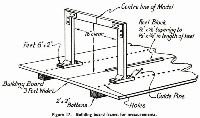
Some preparatory work is advisable and indeed necessary. I take it that the builder will be in possession of, and have carefully studied, the drawings, without a good set of which it is, of course, impossible to build a scale model. A good solid table is the first requisite, placed in the best light in the workshop. Get this table level and then screw it down to the floor with the help of a couple of iron brackets. The table need not be very large. It is only to support the building board, which should be about 6 ft. long and 3 ft. wide. I found ½-in. plywood very satisfactory. Screw some straight 2 X 2 battens on the bottom of the board to keep it stiff; it is absolutely essential that it should remain flat. Level it up meticulously and fix it to the table so that there will be no chance of its shifting. A useful accessory to the building board is a square frame which you can slide along it. Make this frame of planed battens with an inside measurement of 18 in. The frame has only three sides, so that it can slide over the model. The upper corners will be stiffened with brackets and it will be supported on feet about 2 in. wide and 6 in. long. Arrange guides on the board so that the centre of the cross bar of the frame will always correspond with the centre line on the board. You will find this frame very useful in taking and checking measurements. (Fig. 17.)
Now take your time about marking out the board. A centre line is drawn with a scriber so as to be permanent. Scribe other lines parallel with the centre line 1 ft. on each side of the centre line. Now choose the point on the centre line where you want to have the dead flat. At this point scribe a line across the board at right angles to the centre line. Continue to scribe parallel lines fore and aft of the dead flat at the “stations” given in the plan. The stations are the straight lines, parallel with and equidistant from each other which are drawn at right angles with the line of the keel in the half-breadth plan. They are vertical lines in the sheer plan. You cannot be too careful in getting these lines right once and for all from the very start.
Check them over in every possible way to detect any error. After scribing, pencil the lines in. In course of time the pencil marks will fade out and can be renewed when necessary. From the half-breadth plan take off with a pair of dividers the maximum width at each station. Mark these points on each of your station lines. Scribe a line joining all these points. You will find this line very useful later on, but it should be noted that the half-breadth plan gives the “moulded” breadth of the ship. This means the breadth of the frames before the planking is put on, so that if your planking is, say, 3/32 in. thick, your model should be 3/16 in. wider than the plan after it has been planked.
From the sheer plan, take off the length of the keel from the after side of the stern post to the point where the gripe begins to rise from the horizontal. Cut a batten ½ in. wide to this length. Plane it down so that it is ½ in. deep at one end and ¼ in. at the other. Take off the distance from the dead flat to the after end of the stern post and screw the batten exactly on the centre line of the board with the thinner end on the stern position. These ships were built to draw 1 ft. more aft than forward. By building the model on a sloping block you avoid a good deal of complication and you can get the water lines horizontal.
The keel is prepared as a beginning; use an old seasoned straight-grained piece of some hard wood—such as a bit of old mahogany table top. The dimensions are taken off the drawings. Remember that the siding of the keel tapers slightly fore and aft. Gut in it the rabbet for the garboard strake, the mortices for the stern posts and the scarf for the stem. The stern post and inner post are then cut with the tenons; and the rabbet on the stern post is taken out. Then prepare the deadwood. There is no object in building it up of several pieces; it must fit accurately on to the keel and the inner post. To fix it in position, use three thin brass screws through the keel and two through the inner post, but do not make any final fixation as yet. The stem assembly is taken in hand next. So many pieces are used in building up the stem and the knee of the head, every joint holding possibilities of error and weakness, that it is perhaps better, unless the model is meant for demonstration purposes, to make the whole assembly out of a single flat piece of wood. You will be in quite good company in doing so, as most of the contemporary museum pieces were built in this way. If you decide to do so, trace off from the sheer plan, the stem, the knee of the head, and the gripe, together with the boxing where it scarfs on to the fore end of the keel. The gammoning knee can also be included, and it is a good plan to include the after edge of the stemson and the apron below the level of the beak-head platform or deck. I will explain the reason for this later. As the knee of the head rises it becomes thinner athwartship. The gripe is of the same siding as the fore end of the keel and the taper upwards is regular and gradual. Just below the figurehead it is little more than half as thick as at the gripe. Transfer the tracing to a suitable piece of wood. I was fortunate in having by me a good deal of lovely old flat holly, which is a very sweet wood to work and does not split easily. I used quite a bit of it in the framing and planking. For planking it is specially suitable, since it bends kindly and will take a fastening at the end of a plank without splitting. Moreover, in course of time its colour becomes quite unobtrusive. Saw the piece out to the pattern, mark a centre line down the fore edge and then plane it down to the desired siding, but keep the apron and the stem portion of the same thickness throughout the whole length. Cut out a recess or lug upon which the figurehead block will eventually rest, bore the two holes for the bobstays near the fore edge, the hole for the mainstay collar, and cut the slots for the gammoning. Then mark out carefully the line of the rabbet; remember that allowance must be made for the gripe. Do not mark out the rabbet at the lower end, until the scarf with the keel is cut. Fix this joint temporarily and then mark it out so that the rabbet line at the junction of the two pieces will be fair. The front edge of the rabbet for about the upper two-thirds is cut vertically to the surface. The scarf between the keel and the stem piece must be a perfect fit, and truly square, otherwise the stem will not set in a proper vertical line. Fit all the pieces you have made so far together temporarily and test the accuracy of your workmanship by laying them flat on the board with thin wedges under the knee of the head and the ends of the keel to allow for its taper. The whole thing should He flat. It is a good rule to drill any holes which may be needed later on before fixing it in position; that is why I have mentioned various holes to be drilled. Also as a general rule when dead accuracy is imperative in bolting two pieces together, glue them together lightly first and then drill the holes for the bolts. Afterwards they can be knocked apart and when the bolts or pegs are inserted they will always resume their correct position. Otherwise, although you may be meticulously careful in marking out the positions of the holes, a very small deviation of the centre punch or the drill may upset the work. A tremendous amount of this pegging ...
Table of contents
- Title page
- TABLE OF CONTENTS
- LIST OF FIGURES
- LIST OF PLANS
- LIST OF PLATES
- PREFACE
- PART I - THE HULL
- NOTES ON PAINTING OF SHIP
- PART II - THE RIGGING
- REQUEST FROM THE PUBLISHER
Frequently asked questions
Yes, you can cancel anytime from the Subscription tab in your account settings on the Perlego website. Your subscription will stay active until the end of your current billing period. Learn how to cancel your subscription
No, books cannot be downloaded as external files, such as PDFs, for use outside of Perlego. However, you can download books within the Perlego app for offline reading on mobile or tablet. Learn how to download books offline
Perlego offers two plans: Essential and Complete
- Essential is ideal for learners and professionals who enjoy exploring a wide range of subjects. Access the Essential Library with 800,000+ trusted titles and best-sellers across business, personal growth, and the humanities. Includes unlimited reading time and Standard Read Aloud voice.
- Complete: Perfect for advanced learners and researchers needing full, unrestricted access. Unlock 1.5M+ books across hundreds of subjects, including academic and specialized titles. The Complete Plan also includes advanced features like Premium Read Aloud and Research Assistant.
We are an online textbook subscription service, where you can get access to an entire online library for less than the price of a single book per month. With over 1.5 million books across 990+ topics, we’ve got you covered! Learn about our mission
Look out for the read-aloud symbol on your next book to see if you can listen to it. The read-aloud tool reads text aloud for you, highlighting the text as it is being read. You can pause it, speed it up and slow it down. Learn more about Read Aloud
Yes! You can use the Perlego app on both iOS and Android devices to read anytime, anywhere — even offline. Perfect for commutes or when you’re on the go.
Please note we cannot support devices running on iOS 13 and Android 7 or earlier. Learn more about using the app
Please note we cannot support devices running on iOS 13 and Android 7 or earlier. Learn more about using the app
Yes, you can access The Anatomy of Nelson's Ships by Dr. C. Nepean Longridge in PDF and/or ePUB format, as well as other popular books in History & British History. We have over 1.5 million books available in our catalogue for you to explore.