Workshop Machining is a comprehensive textbook that explains the fundamental principles of manually operating machinery to form shapes in a variety of materials. It bridges the gap between people who have traditional toolmaking skills and those who have been trained in programming and operation of CNC machines in a focused production environment, rather than general machine shop.
Using a subject-based approach, David Harrison intuitively guides readers and supplies practical skills. The chapters cover everything from the basic machine controls to advanced cutting operations using a wide range of tooling and work-holding devices. Theory and practice are shown via a mixture of diagrams, text and illustrated worked examples, as well as through exercises.
The book is ideal for students and lecturing staff who participate in, or lead, practical machining sessions, and for those who wish to further develop their machining skills. It also serves as an excellent reference to understand the principles and limitations of producing shapes with cutters that move in a limited combination of linear and radial paths.
Trusted by 375,005 students
Access to over 1.5 million titles for a fair monthly price.
As technology continually advances through all walks of life manufacturing machining has also undergone a similar step change in capability. The introduction of computer controlled machinery has allowed profiles to be machined that were previously obtainable other than through a series of protracted operations and a degree of hand finishing. With the introduction of computer numeric controlled (CNC) machines productivity had a step change increase as has precision and repeatability.
However, with this improvement, have we lost anything? The answer to this is a qualified yes. Modern manufacturing often involves the creation of a computer program either remotely or directly entered into a machine. The closest machinists come to the process of machining is observing metal cutting happening inside a cloud of coolant through the closed door of a CNC or a tool path graphic on the machine display. The close connection to seeing and feeling exactly what is happening at the tool point, and the direct relationship between a machine operator directly controlling how metal is cut, is being eroded.
The intention of this book is to bridge the widening gap in knowledge between people who once learned skills through traditional four-year tool-making apprenticeships, and those who are trained to program and operate CNC machines in a production environment. It is intended to support apprentices, students, and lecturing staff who would like to participate in, or lead, practical sessions, and for those who want to develop an understanding of the principles and limitations of producing shapes with cutters that move in a limited combination of linear paths. It is also intended to provide a starting point for those who wish to broaden their skills from one machining discipline to another, and assist the hobbyist in taking their first steps along a path from basic turning and milling, to machining more complex components.
Workshop Machining is a comprehensive textbook that explains the basic principles of manually operating machinery to form shapes in a variety of materials through a subject based approach for those who wish to develop both practical skills. The theory and practice will be shown through a mixture of diagrams, text and illustrated worked examples.
The contents of the book are broken down into five sections covering turning, milling, surface grinding, cylindrical grinding, and drilling. Each of those sections is structured in a way that introduces the reader to the machine and how it operates. The tooling that is used on it and the method of basic operation. There are further chapters in each section that identify how to operate more complex tooling, work holding techniques and alternative approaches. Common problems encountered when undertaking each type of machining are identified and have suggestions for resolution.
Located in the appendices are a number of simple and more complex machining exercises that are intended to introduce the reader to machining shapes in basic materials on a lathe and milling machine. Two simple tasks are intended to provide the reader with drawings and a step by step guide to machining the object, to give the operator confidence in using a lathe and a milling machine.
It is hoped that the following pages provide a useful reference for experienced machine operators, a ‘how to’ reference source for those wishing to deepen their knowledge of aspects of machining, and an introduction to material removal techniques for those taking their first steps in the wider world of the general engineering workshop.
Chapter 2
Degrees of freedom
DOI: 10.1201/9780429298196-2
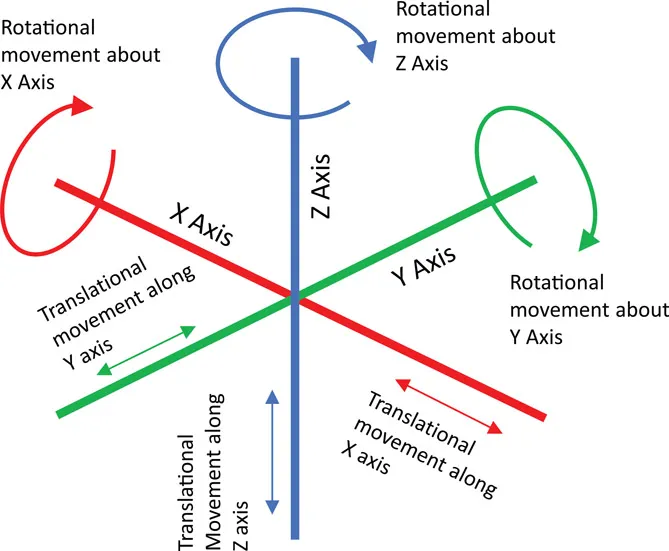
Every machine tool has the capability to undertake a combination of translational movements and rotary movements, and it uses these to allow a cutter to be applied to a workpiece in order to shape it. The term that describes this is kinematics, or the study of motion without reference to force or mass. While there are a number of equations that can be employed to solve a problem, these tend, in a manufacturing environment, to be more of concern to robotics. However, its relevance to machining is that the combination of rotary movement and translational movement is what allows us to undertake the reductive process that is machining. Figure 2.1 identifies the six possible translational and rotational movements known as ‘degrees of freedom’.
Figure 2.1
Six degrees of freedom
Each type of machine will have constraints imposed on it by the number of degrees of freedom, and that is why we often use multiple types of machines to produce a desired component. Modern computer numeric controlled (CNC) machines are capable of utilising five degrees of freedom simultaneously and are capable of producing complex developed shapes, that are either impossible to produce on manual machinery, or extremely time consuming especially to the level of accuracy achievable on a five-axis CNC machine.
Machine axis are defined on a common basis. Typically a milling machine will have the x-axis making translational movements to the left and right of the operator. The y-axis makes translational movements away from, and towards the operator, and the z-axis relates to translational movements made in the vertical plane. However on a lathe this differs with the z-axis making translational movements to the left and right of the operator along the axis of the machine, and the x-axis applying the cut moving away and towards the operator.
Chapter 3
Turning
DOI: 10.1201/9780429298196-3
Turning as a process is almost exclusively undertaken on a centre lathe. Turning differs from other types of machining as it is the workpiece that rotates rather than the cutter. Its function is to produce workpieces that are shaped into round components, generally, although not exclusively sharing the same central axis.
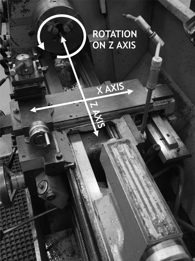
The lathe is one of the oldest tools that craftsmen have utilised to produce items, with some evidence to suggest turning on a lathe could date back as far as 1300 BC. While there is some evidence for this, and much stronger evidence to suggest that turning as a process was being undertaken in 400 BC, the centre lathe that engineers would recognise came into being in the 18th century. This type of machine has three degrees of freedom with a translational movements provided along the x- and z-axis and a single rotational movement along the z-axis. Figure 3.1 shows the notation of lathe axis on a centre lathe.
Figure 3.1 Lathe axis notation
All machine shop lathes have the same basic configuration which consists of:
Headstock. This consists of the chuck or principal work holding device, motor, gearbox and central spindle. It also has all of the ancillary controls such as speed selection, coolant on/off switch, gear selectors for configuring screw cutting settings, and feed speeds.
Bed. This is a ground trackway which forms the principal chassis of the machine to allow the tool to be moved along the axis of the machine. It is generally manufactured from cast iron and is required to be very stiff to accommodate the loads imparted to it when machining.
Saddle. This is mounted upon the ground trackway of the bed and is used to move the cross slide, compound slide, and tool post along the axis of the machine. Attached to the saddle are the controls for manually moving the saddle along with levers to operate the automatic feed mechanism and engage the lead screw where fitted.
Cross slide. This sits on top of the saddle mounting the compound slide and tool post, and is used to move the tool across the axis of the machine.
Compound slide. This mounts the tool post and is capable of being rotated to allow generation of features at any angle across the plane of the machine bed. This overcomes the single angle restrictions of the saddle and cross slide. A significant feature of the compound slide is a circular base engraved with a scale most commonly using whole degrees.
Tool Post. This is the clamping device for holding the cutting tool. They come in a number of designs, which mount a single tool, or are of a more complex design such as those that allow for four tools to be mounted at 90 degrees to each other and can be indexed round using a simple lever, or are of the ‘quick release’ type allowing multiple positions of tools but are principally designed to allow quick changes of a tool carrier to facilitate changes of tool types for differing operations. They all have their strengths and weaknesses but the essential function is the same: to mount a cutting tool on centre height so that it can be addressed in the correct configuration to the workpiece.
Tailstock. This is mounted on the ground slide way of the bed of the machine at the opposite end to the headstock. It consists of a cast body, containing an extending cylinder or quill which can be extended from the body using a hand wheel. Its function is to mount a separate chuck to facilitate drilling, or to mount a live or dead centre to support long workpieces. It is able to be moved along the bed to a desired position and locked in place. The centre height of the tailstock cylinder is exactly that of the axis of the machine, and it also has adjusting screws built into the body to allow transverse adjustment to ensure the centre is completely aligned in two planes. The significance of having a tailstock properly aligned with machine axis, is that if improperly set up then when machining material supported by a centre the result is a tapered workpiece.
While centre lathes come in all shapes and sizes from a small bench top modelling lathe to substantial machines with beds that are many meters long, they all operate using the same principles. While size makes a difference for the depth of cut that can be undertaken in a single pass, the length of bed constrains the longest component that can be machined and the height of the axis above the bed which limits the ‘throw’ of the machine, it is the accuracy of the machine and the surface finish that can be obtained which is most affected by size.
The accuracy of all lathes is a function of the precision to which they were manufactured and the combination of slide way screw pitches, and marking of the scales on control wheels. Small cheap machines tend to be less robust, and the diameter of the control screws and hand wheels tend to be less precise than larger machines. That said there are some extremely precise and commensurately expensive, machines available, however, these tend to be more directed at specialist markets than general engineering. The size of the machine is also often key to accuracy. A very large machine such as that used for turning ships propellor shafts is often poor at machining small diameter components, so the size of machine used needs to be matched within a sensible parameter to achieve the accuracy required. A ‘standard’ workshop centre lathe in reasonable condition with a bed of approximately 750–1000mm and a throw of approximately 200mm should have little problem in achieving an accuracy of 0.02mm or better.
Surface finish that can be achieved on a lathe is a combination of a considerable number of factors all of which have a direct impact on the surface finish achieved. However, assuming that all factors have been optimised then achieving a surface finish of between 12.5–1.6µm with 3.2µm being considered a smooth turned finish. Factors that can (adversely) affect surface finish include the following:
rotational speed;
tool type;
feed;
material type;
tool holding rigidity;
work ...
Table of contents
Cover Page
Half Title Page
Title Page
Copyright Page
Contents Page
Acknowledgements Page
1 Introduction
2 Degrees of freedom
3 Turning
4 Milling
5 Surface grinding
6 Cylindrical grinding
7 Drilling
Appendix A: Nomogram for calculation of helical milling angles
Appendix B: Simple turning exercise
Appendix C: Simple milling exercise
Index
Frequently asked questions
Yes, you can cancel anytime from the Subscription tab in your account settings on the Perlego website. Your subscription will stay active until the end of your current billing period. Learn how to cancel your subscription
No, books cannot be downloaded as external files, such as PDFs, for use outside of Perlego. However, you can download books within the Perlego app for offline reading on mobile or tablet. Learn how to download books offline
Perlego offers two plans: Essential and Complete
Essential is ideal for learners and professionals who enjoy exploring a wide range of subjects. Access the Essential Library with 800,000+ trusted titles and best-sellers across business, personal growth, and the humanities. Includes unlimited reading time and Standard Read Aloud voice.
Complete: Perfect for advanced learners and researchers needing full, unrestricted access. Unlock 1.5M+ books across hundreds of subjects, including academic and specialized titles. The Complete Plan also includes advanced features like Premium Read Aloud and Research Assistant.
Both plans are available with monthly, semester, or annual billing cycles.
We are an online textbook subscription service, where you can get access to an entire online library for less than the price of a single book per month. With over 1.5 million books across 990+ topics, we’ve got you covered! Learn about our mission
Look out for the read-aloud symbol on your next book to see if you can listen to it. The read-aloud tool reads text aloud for you, highlighting the text as it is being read. You can pause it, speed it up and slow it down. Learn more about Read Aloud
Yes! You can use the Perlego app on both iOS and Android devices to read anytime, anywhere — even offline. Perfect for commutes or when you’re on the go. Please note we cannot support devices running on iOS 13 and Android 7 or earlier. Learn more about using the app
Yes, you can access Workshop Machining by David Harrison in PDF and/or ePUB format, as well as other popular books in Technology & Engineering & Industrial Design. We have over 1.5 million books available in our catalogue for you to explore.