The book provides a comprehensive overview of Single-Inductor Multiple-Output Converters from both theoretical and practical perspectives. Based on the authors' in-depth research, the volume covers not only conventional SIMO DC-DC converters but also the new generations of SIMO such as SIMO AC-DC converters, SIMO DC-AC converters (or SIMO inverters), and the latest SIMO hybrid converters.
This book offers a holistic and systematic presentation of all types of SIMO converters, encompassing the derivation of the circuit topologies, the definition of key concepts, detailed discussion of theoretical underpinnings, design methodology and control schemes, as well as design considerations and techniques that enable practical implementation. Specific examples of real-world applications of SIMO converters are also provided. The volume offers a comprehensive overview and systematic classification of the traditional and modern topologies of SIMO converters in terms of system architecture, circuit analysis, operating principles, control methods, design considerations and practical implementation. Specifically, the book
presents the mathematical models and design principles necessary for analyzing the behavior of each kind of SIMO converter, and building upon that, introduces and imparts new approaches and techniques when designing such converters, guiding engineering students and power engineers towards achieving low-cost, compact and energy efficient SIMO converters.
offers the design considerations and optimization as well as describing the key applications of SIMO converters.
The book fills a significant niche in the power electronics literature and provides a complete perspective on SIMO converters that hopefully can inspire appreciation and better understanding of the subject matter. It can be directly adopted in undergraduate or graduate coursework as well as postgraduate research programs.
Trusted by 375,005 students
Access to over 1.5 million titles for a fair monthly price.
CHAPTER1Introduction to Single-Inductor Multiple-Output Converters
DOI: 10.1201/9781003239833-1
1.1 Introduction to SIMO Topology
To our best knowledge, the advent of single-inductor multiple-output (SIMO) DC-DC converters can be dated as far back as 1997, the year when a U.S. patent application of a SIMO boost regulator was filed, and subsequently, a US patent was published on June 13, 2000 [1]. Soon afterwards, an increasing number of conference papers and journal articles related to SIMO DC-DC converters were published [2,3,4,5,6,7,8,9,10,11,12,13,14,15,16,17 and 18]. Many electronic devices or systems require multiple regulated supply voltages for different function modules. Dynamic voltage scaling (DVS) is a common technique to reduce the average power consumption in embedded systems. DVS is typically used in battery-operated portable electronic devices such as mobile phones, tablets, wearables, and sensors where power savings and battery life are paramount. It is also used in large systems with multiple microprocessors or digital signal processors where power saving is needed for thermal management.
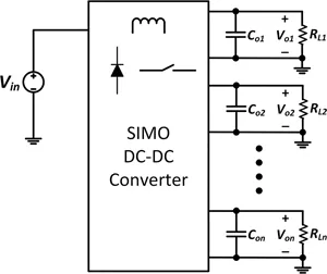
Conventionally, to provide multiple supply voltages, a straightforward approach is to use multiple independent switching converters. In general, N single-output switching converters are employed to generate N regulated output voltages. This requires a total of N inductors and 2N power devices (power MOSFETs and diodes). Figure 1.1 shows the system architecture of a conventional implementation using multiple DC-DC switching converters. With the advancement of semiconductor technologies, power MOSFETs, gate drivers, and control circuits are usually integrated. Unfortunately, off-chip inductors are still the bulkiest and perhaps, one of the most expensive components in switch mode power supply (SMPS), which pose a huge challenge in the miniaturization of DC-DC converters. On the other hand, to provide galvanic isolation between the input and multiple outputs of an isolated multiple-output flyback converter with a single controller, a transformer with one primary winding and multiple secondary windings can be used. In most cases, the voltage of the master output, typically the one with the heaviest load, is tightly regulated via closed-loop control while the other outputs are loosely controlled (or “quasi-regulated”) through coupling of the secondary windings. It is susceptible to cross-regulation as a change in the master output will also affect the other outputs. Yet both implementations inevitably require the use of bulky magnetics, which are difficult to integrate. Driven by a strong desire to achieve small size, light weight, and low cost for multiple-output converters, considerable research efforts have been devoted to exploring new circuit topologies using only one inductor to supply multiple outputs. Ultimately, this has led to the invention of a new circuit topology called SIMO. The use of a single inductor to drive multiple unidentical loads has quickly emerged as a highly scalable and promising solution for space-constrained and cost-conscious applications. Figure 1.2 shows the system architecture of a SIMO DC-DC converter.
FIGURE1.1 System architecture of a conventional implementation using multiple DC-DC switching converters.
FIGURE1.2 System architecture of a SIMO DC-DC switching converter.
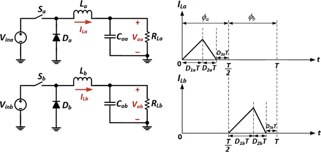
As an example, let us consider two conventional DC-DC buck switching converters, namely, Converter A and Converter B, with the same switching frequency fs. Both converters operate in discontinuous conduction mode (DCM). The on-time period of the power switch of the two converters is denoted by D1aT and D1bT, respectively, where Ts is the switching period (Ts = 1/fs). Suppose the two converters work in two complementary phases ϕa and ϕb in such a way that D1aT + D2aT < 0.5 and D1bT + D2bT < 0.5. Figure 1.3 depicts the circuit diagrams and the corresponding waveforms of the inductor currents of the two buck converters in DCM.
FIGURE1.3 Circuit diagrams and inductor current waveforms of the two buck switching converters.
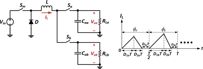
For Converter A, the inductor current ramps up during the first subinterval (D1aT) as the inductor is charged. It ramps down during the second subinterval (D2aT) as the inductor is subsequently discharged. Finally, it returns to zero during the third subinterval (D3aT), where D3aT = 1 − D1aT − D1bT. DCM is characterized by the inductor current being zero in the third subinterval (the so-called idle phase). Likewise, Converter B also has a similar switching sequence. Since the power switches Sa and Sb are enabled in ϕa and ϕb, respectively, the energy is diverted to the two outputs Voa and Vob in separate time intervals. As a consequence, the operations are fully decoupled in the time domain and thus independent of each other. Hence, the two buck converters can essentially be combined into a single buck converter whose circuit diagram and inductor current waveform are depicted in Figure 1.4.
FIGURE1.4 Circuit diagram and inductor current waveform of SIDO buck converter operating in DCM.
Figure 1.4 shows that two complementary output switches Sa and Sb are used to select which output to connect to the main inductor L. It is crucial to note that Sa and Sbcannot be simultaneously switched on under all circumstances. Sa is switched on only during the first phase ϕa, while Sb is switched on only during the second phase ϕb. In other words, the energy stored in the inductor is transferred to the two outputs successively in a round-robin time-multiplexing (TM) manner. The so-called TM switching scheme enables the sharing of a single inductor between the two outputs without any cross-channel interference, which is also referred to as cross-regulation. In this way, a single-inductor dual-output (SIDO) converter is obtained. For ease of modeling and analysis, the SIDO converter operating in DCM can be functionally decomposed into two individual subconverters. The feedback controller of each subconverter can then be designed separately.
Naturally, we can extend this TM switching scheme to an arbitrary number of outputs. Each output will be allocated a uniform time slot of T/N for the charging and discharging of the inductor, where N is the number of outputs. Simply put, the inductor is being charged (or discharged) N times within a full period T. Such switching scheme is referred to as the multiple-energizing method. Hence, this gives rise to a whole new family of SIMO converters.
Nonetheless, a major drawback of operating the SIMO converter in DCM is that the output current is relatively small. This implies that the output power that can be delivered by the SIMO converter is rather limited. In DCM, the only way to achieve a higher output current is to increase the peak value of the inductor current at a fixed switching period. But this inevitably leads to an increase in the current stress of the inductor and power MOSFET(s). Ultimately, the maximum peak current is reached when the SIMO converter operates at the boundary conduction mode (BCM) or critical conduction mode, which is a boundary condition between continuous conduction mode (CCM) and DCM. To address the issues of power limitation and increased current stress, a new operating mode named pseudo-continuous conduction mode (PCCM) is introduced primarily for SIMO switching converters [5]. In PCCM, the floor of the inductor current is raised by a DC level of Idc, which effectively increases the average value of the inductor current. This is made possible with the addition of a freewheel switch across the inductor. Figure 1.5 shows a SIDO converter and the corresponding inductor current waveform in PCCM. To meet the high current demand of heavy loads, Idc can be increased to allow more power to be delivered to the outputs. Compared to DCM, the inductor current ripple ∆IL can be much reduced as a larger inductor can be used in PCCM. Thus, the power constraints incurred in DCM can be safely eliminated, and the converter can achieve relatively small current and voltage ripple. In short, by operating the SIMO converter in PCCM, the output power can be increased while maintaining zero cross-regulation. Chapter 2 focuses on SIMO DC-DC converters and their operating principle.
FIGURE1.5 Circuit diagram and inductor current waveform of SIDO converter operating in PCCM.
The predecessors of SIMO converters are designed specifically for DC-DC power conversion. From a single DC power source (e.g., a battery cell), they can produce multiple DC output voltages by employing only a single inductor in the power stage. A number of on-chip SIMO DC-DC boost converters with only one off-chip inductor were reported in the literature [3,4,5,6 and 7]. Compared with the traditional multiple-output converter topologies, these SIMO converters require fewer inductors, power devices, and control loops, which carry the advantages of small form factor, reduced component count, low build-of-material cost, better scalability to multiple outputs, and high efficiency. The SIMO DC-DC converters can be used in a number of key applications, including, but not limited to, voltage regulator modules, system-on-chips (SoCs), and embedded power supplies for a myriad of mobile devices. In addition, SIMO DC-DC converters can also act as SIMO LED drivers for supplying multiple independent LED strings. This helps extend the scope of applications of SIMO, which include LED backlighting for LCD displays as well as ambient lighting and intelligent color-mixing applications via red-green-blue (RGB) LED lighting...
Table of contents
Cover
Half Title
Title Page
Copyright Page
Table of Contents
Chapter 1 ◾ Introduction to Single-Inductor Multiple-Output Converters
Yes, you can cancel anytime from the Subscription tab in your account settings on the Perlego website. Your subscription will stay active until the end of your current billing period. Learn how to cancel your subscription
No, books cannot be downloaded as external files, such as PDFs, for use outside of Perlego. However, you can download books within the Perlego app for offline reading on mobile or tablet. Learn how to download books offline
Perlego offers two plans: Essential and Complete
Essential is ideal for learners and professionals who enjoy exploring a wide range of subjects. Access the Essential Library with 800,000+ trusted titles and best-sellers across business, personal growth, and the humanities. Includes unlimited reading time and Standard Read Aloud voice.
Complete: Perfect for advanced learners and researchers needing full, unrestricted access. Unlock 1.5M+ books across hundreds of subjects, including academic and specialized titles. The Complete Plan also includes advanced features like Premium Read Aloud and Research Assistant.
Both plans are available with monthly, semester, or annual billing cycles.
We are an online textbook subscription service, where you can get access to an entire online library for less than the price of a single book per month. With over 1.5 million books across 990+ topics, we’ve got you covered! Learn about our mission
Look out for the read-aloud symbol on your next book to see if you can listen to it. The read-aloud tool reads text aloud for you, highlighting the text as it is being read. You can pause it, speed it up and slow it down. Learn more about Read Aloud
Yes! You can use the Perlego app on both iOS and Android devices to read anytime, anywhere — even offline. Perfect for commutes or when you’re on the go. Please note we cannot support devices running on iOS 13 and Android 7 or earlier. Learn more about using the app
Yes, you can access Single-Inductor Multiple-Output Converters by Albert Ting Leung Lee,Weijian Jin,Siew-Chong Tan,Ron Shu Yuen Hui in PDF and/or ePUB format, as well as other popular books in Technology & Engineering & Electrical Engineering & Telecommunications. We have over 1.5 million books available in our catalogue for you to explore.