CNC control of milling machines is now available to even the smallest of workshops. This allows designers to be more ambitious and machinists to be more confident of the production of parts, and thereby greatly increase the potential of milling at home.This new accessible guide takes a practical approach to software and techniques, and explains how you can make full use of your CNC mill to produce ambitious work of a high standard. Includes: Authoritative advice on programming and operating a CNC mill; Guide to the major CAD/CAM/CNC software such as Mach3, LinuxCNC and Vectric packages, without being restricted to any particular make of machine; Practical projects throughout and examples of a wide range of finished work; A practical approach to how you can make full use of your CNC mill to produce ambitious work. Aimed at everyone with a workshop - particularly modelmakers and horologists. Superbly illustrated with 280 colour illustrations. Dr Marcus Bowman has been machining metal for forty years and is a lifelong maker of models, clocks and tools.
- 144 pages
- English
- ePUB (mobile friendly)
- Available on iOS & Android
eBook - ePub
CNC Milling in the Workshop
About this book
Trusted by 375,005 students
Access to over 1 million titles for a fair monthly price.
Study more efficiently using our study tools.
Information
1 Fundamental Concepts
In this chapter you will learn about:
- the process of getting from a design to a finished workpiece;
- details of the software systems you might use;
- some of the mechanical and electronic systems used in CNC milling machines.
FROM DESIGN TO COMPLETED PROJECT
The traditional explanation of what happens in the workshop is that an idea is turned into a pencil sketch on the back of an old envelope, and a machinist uses that information to produce a finished workpiece while standing at the mill.
That romantic and rather unrealistic view of the process needs some refinement for a CNC machine. Fig. 1-1 shows the stages in the journey from design to completed workpiece, indicating the relative contribution of a human (on the left) and a computer (on the right). The original idea, for example, is an entirely human contribution, whereas creating the program may require both human and computer contributions.
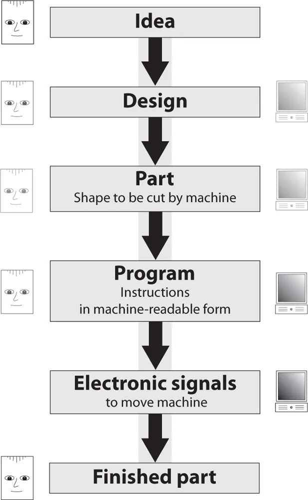
Fig. 1-1 The main software functions associated with a CNC system.
From a software point of view, there are three main stages in the process: create a design, turn the design into data and use the data to control a machine. These correspond to the conventional computer-aided design (CAD), computer-aided manufacture (CAM) and computer numerical control (CNC) stages shown in Fig. 1-2.
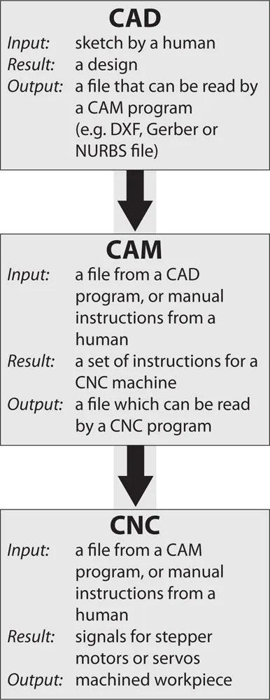
Fig. 1-2 Stages in the CAD/CAM/CNC process.
Creating a Design
Unlike the rough sketch on a small piece of paper, the design stage must result in a completely specified design in which all the geometric features are present, accurately sized and precisely positioned. Whether the design is produced on paper or on a computer monitor depends on the complexity of the design and the nature of the features.
Some designs consist of simple arrangements of easily defined shapes such as straight lines and circles, but anything other than the simplest of shapes will benefit from the use of appropriate design software.
The design shown in Fig. 1-3 is a simple shape that could be fully specified on a small piece of paper and hand coded directly into the editor of a CNC package without much trouble.
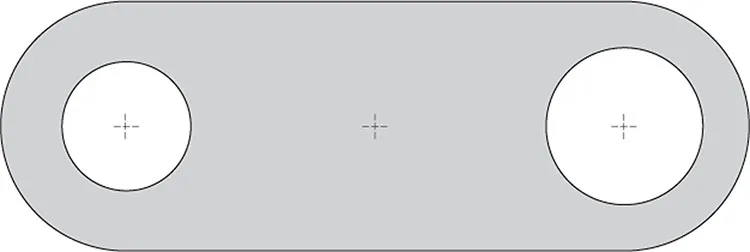
Fig. 1-3 A geometrically simple shape.
The design shown in Fig. 1-4 is an apparently simple design that can easily be sketched on paper, but cannot be fully specified without some significant mathematical calculations to identify the intersection points at A and B. Without those points, there is insufficient information to be able to create a CNC program.
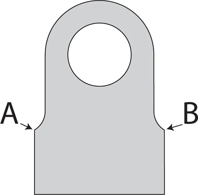
Fig. 1-4 A shape that appears simple, but includes a geometric complexity.
The design shown in Fig. 1-5 is of a visually and geometrically rich object (a set of clock plates) that might be sketched on paper, depending on the skill of the artist, but because of the complex curves, it would take a very considerable effort to fully specify the geometry and a mastery of advanced mathematics to calculate and prepare the data required for a CNC machine.

Fig. 1-5 A clock plate – a geometrically rich and complex shape.
In fact, the design process itself is severely compromised if it is restricted to designs that can be sketched on paper and hand coded as CNC programs. On the other hand, consistent use of CAD software allows most designs to be created with relative ease and for those designs to incorporate features that might enhance the visual appeal of the design, in the knowledge that those additional features can be produced easily in the CAM and CNC stages of the process, usually for little additional human effort.
Figs 1-6 and 1-7 show two versions of a design for a support bracket for a toolpost grinder. The first, in Fig. 1-6, is based on a geometrically simple shape that can be specified on paper and hand coded. The second version, in Fig. 1-7, contains enhancements to the design to improve the usefulness of the object as well as its aesthetic appeal. This second version was designed in a CAD package, coded by CAM software, and machined using a CNC program. Fig. 1-8 shows the bracket in use. Once drawn in a CAD package, even geometrically complex objects can easily be produced by employing a CAM package to do the sophisticated mathematics required for the toolpaths and a CNC package to follow the instructions generated by the CAM package.
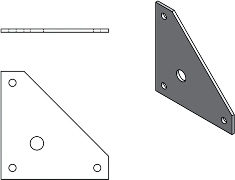
Fig. 1-6 A simple bracket.
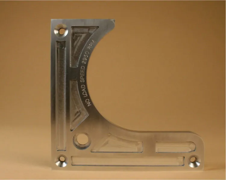
Fig. 1-7 An enhanced version of the bracket.
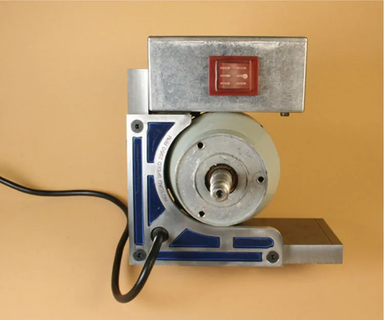
Fig. 1-8 The enhanced bracket in use on a toolpost grinder (note: wheel and guard removed for clarity).
2D design software has been in use since the early 1970s and ranges from simple freeware to powerful industry-standard proprietary packages. While there are many design packages, there are some important factors in the choice of package to use. In a CAD/CAM/CNC system, each stage in the process must be able to communicate with the next stage and this guides the choice of packages.
AutoCAD was an early entrant to the 2D design market on personal computers and its native DWG file format has become one of the standards for file interchange for drawings being passed between CAD and CAM systems. AutoCAD’s DXF file format (the Drawing eXchange Format) is another widely used file format for communicating data between the CAD and CAM stages of the CAD/CAM/CNC cycle.
These two file formats are widely recognized by all the useful drawing programs, to the extent that any drawing program not supporting these formats is not likely to be of use in the drawing office or the workshop.
Fortunately, a number of programs support these formats, so the choice is wide. Today, AutoCAD LT continues to be popular, but TurboCAD, DraftSight (free), and many others are all capable of producing 2D DXF drawing files.
2D drawing packages deal with flat shapes, such as parts made from sheet metal. 3D drawing packages deal with shapes such as a human head, or all sides of a locomotive smokebox, or the front, rear and sides of a car wheel.
2D shapes are useful, but relatively flat and featureless. True 3D shapes are difficult to hold for machining, especially if there are features to be cut on all sides like a 3D map of the world, for example. So, 2½D is the most useful kind of shape because, although based on a flat surface, the ability to machine down into the surface at any point allows designs for shapes that are like 3D but without features on the rear. Those shapes can be held on a conventional milling machine and they can be machined from one side, using movements along X, Y and Z axes.
While 2½D shapes are most common, some readily available software allows fully 3D shapes to be made from 2½D shapes by machining one side, then turning over and machining the reverse side so that the basic 2½D machining movements produce a fully 3D object.
Cut2D
The Vectric Cut2D package is one example of a CAD/CAM package that will allow simple 2½D machining with relative ease. It takes a DXF drawing, or allows the user to draw shapes within the program itself, then outputs the code required for separate CNC software to control a machine. Although there is more work required from the user in dealing with a 2½D object, the way in which the software does its job is essentially the same, whether the object is 2D or 2½D. The limitations on the program are that machined areas should generally have a flat bottom or that the shape of the bottom is formed by the shape of the end of the cutter (for example, a ball-nosed cutter producing a rounded groove).
In the CAD/CAM/CNC sequence, both the CAD design stage and the CAM stage using Cut2D are relatively straightforward. More fully shaped objects, contoured along the Z axis, require more sophisticated CAD software, such as Inventor or Solidworks, and more capable CAM software, such as Cut3D, VCarve Pro, PhotoVCarve, or Aspire.
VCarve Pro
This software package adds the capability of full 2½D machining and a more extended range of drawing tools. The more challenging part of the CAD/CAM/CNC sequence then becomes the CAD first stage, where the design is conceived, while the CAM stage is relatively easy, compared to the complexity of the design.
Other 2D and 3D CAD and CAD/CAM Software
Typical 2D CAD software includes Draft-Sight, RhinoCAD, AutoCAD and TurboCAD as well as vector drawing packages, such as Adobe Illustrator. Bit-mapped drawing packages, such as Adobe Photoshop, are not suitable for conventional CAD functions, although you will read later about some specialized applications that may benefit from bit-mapped images or drawing software. Typical 3D software includes Inventor, Solidworks and TurboCAD Pro.
There are references to AutoCAD, Turbo-CAD, Adobe Illustrator, Inventor and Solidworks in this book, but other similar packages may be used to achieve the same result.
Preparing for Manufacture
On...
Table of contents
- CNC Milling In The Workshop
- Contents
- Introduction
- 1 Fundamental Concepts
- 2 The Controlled Point
- 3 Basic Movement
- 4 Tooling
- 5 Linear Programming
- 6 Arcs, Circles and Polylines
- 7 Subroutines, Loops and Decisions
- 8 Making Multiple Parts
- 9 Tool Tables, Cutter Compensation and Tool Length Offsets
- 10 Engraving
- 11 From 2½D to 3D
- Appendix I
- Appendix II
- Appendix III
- Further Information
- Index
- Index of Commands
Frequently asked questions
Yes, you can cancel anytime from the Subscription tab in your account settings on the Perlego website. Your subscription will stay active until the end of your current billing period. Learn how to cancel your subscription
No, books cannot be downloaded as external files, such as PDFs, for use outside of Perlego. However, you can download books within the Perlego app for offline reading on mobile or tablet. Learn how to download books offline
Perlego offers two plans: Essential and Complete
- Essential is ideal for learners and professionals who enjoy exploring a wide range of subjects. Access the Essential Library with 800,000+ trusted titles and best-sellers across business, personal growth, and the humanities. Includes unlimited reading time and Standard Read Aloud voice.
- Complete: Perfect for advanced learners and researchers needing full, unrestricted access. Unlock 1.4M+ books across hundreds of subjects, including academic and specialized titles. The Complete Plan also includes advanced features like Premium Read Aloud and Research Assistant.
We are an online textbook subscription service, where you can get access to an entire online library for less than the price of a single book per month. With over 1 million books across 990+ topics, we’ve got you covered! Learn about our mission
Look out for the read-aloud symbol on your next book to see if you can listen to it. The read-aloud tool reads text aloud for you, highlighting the text as it is being read. You can pause it, speed it up and slow it down. Learn more about Read Aloud
Yes! You can use the Perlego app on both iOS and Android devices to read anytime, anywhere — even offline. Perfect for commutes or when you’re on the go.
Please note we cannot support devices running on iOS 13 and Android 7 or earlier. Learn more about using the app
Please note we cannot support devices running on iOS 13 and Android 7 or earlier. Learn more about using the app
Yes, you can access CNC Milling in the Workshop by Marcus Bowman in PDF and/or ePUB format, as well as other popular books in Technology & Engineering & Mechanical Engineering. We have over one million books available in our catalogue for you to explore.