Screwcutting is a guide to the theory and practice of threads and thread-making, whether that is threading a hole using hand tools or cutting a thread using a lathe. The book covers details of the major threadforms, such as metric, Whitworth and Unified threads, as well as the British Association (BA) and Model Engineering (ME and MME) series, the smaller metric and Unified threads, pipe threads, and specialist threads such as ACME, trapezoidal and RMS microscope threads. Techniques for making threads manually, as well as screwcutting in the lathe are also covered. As well as covering the basics of screwcutting, this book examines higher-level and advanced techniques, using case studies to demonstrate what can be achieved - fine, accurate and well-finished work. Illustrated throughout.
- 304 pages
- English
- ePUB (mobile friendly)
- Available on iOS & Android
eBook - ePub
Screwcutting
About this book
Trusted by 375,005 students
Access to over 1 million titles for a fair monthly price.
Study more efficiently using our study tools.
Information
1 From Beginning to End
The helical groove and ridge form the basis of the screw thread, and, like the wheel or the lever, the origins of this device have been lost in the mists of time. Some historians say wooden screws were in use as early as 400bc, but metal screws did not appear until the 1600s, echoing developments in materials and especially cutting tools capable of machining metals.
The lathe has an older history, dating back some 3,000 years to early applications shaping rotating pieces of wood with a hand-held chisel. Threads lent themselves to being cut on a lathe, using a chisel guided by hand.
Although wood is soft, a great deal of skill is required to cut a thread with sufficient accuracy that the screw will turn in a mating nut. Despite that, some woodworkers still cut threads by hand in the present day, although more as an exercise of skill than as a commercial proposition.
Early applications made use of the fact that a screw rotating in a fixed nut causes the screw to move through the nut, converting rotary motion to linear motion and providing some mechanical advantage. Whereas it may be difficult to push a rod forwards against a load, rotating a screw is easier, even if it does demand a greater rotary movement in many cases. Applications include wine pressing (from earliest times) through the printing press (fifteenth century) to present-day fasteners and precision movements of machine parts such as tables and slides.
Despite being a simple device, the screw thread has been of critical importance in the development of industrial processes and applications. As the industrial revolution dawned and techniques of mass production were developed, thread production not only moved towards the use of standards and the production of interchangeable parts, but, many would argue, drove key developments in manufacturing technology.
In 1568, the French mathematician Jacques Besson invented the first screw-cutting lathe by using pulleys to co-ordinate the longitudinal movement of the tool with the rotation of the spindle.
In the mid-1700s, Antoine Thiout improved on Besson’s method by adding a screw drive instead of pulleys to control longitudinal movement of the toolpost and carriage on a lathe. This was a significant development, laying the groundwork for the kind of accurate tool movement imparted by the modern-day lead screw. To extend the range of movement available with a single pitch screw, Thiout used a system of levers to vary the effective pitch of the main screw. An example of Thiout’s machine can be seen in Paris, in the Musée des Arts et Métiers.
In the 1770s, Jesse Ramsden (1735–1800), the English mathematician and renowned instrument maker, improved the lathe as a screwcutting machine, and that led ultimately to Henry Maudsley’s screwcutting lathes incorporating increasingly accurate leadscrews as well as change gears. That led to his ability to cut accurate micrometer screw threads, creating a simple means of making accurate measurements.
Once accurate screwcutting lathes became available, manufacturers began producing threads to their own specifications, with little interchangeability between systems.
To address this problem, Joseph Whitworth proposed a system of standardized threads based on a 55-degree flank angle and a standard number of threads per inch for each diameter of thread. This led to the British Standard Whitworth system of threads being adopted in Britain in 1841, which proved to be a critical moment in the development of standards for the interchangeability of parts in mass production.
In the USA, William Sellers proposed a similar system based on a threadform with 60-degree flank angle, and that led to the Unified Thread Series standard on which the popular Unified series of threads is based.
In more recent times the almost universal adoption of ISO thread standards, and of ISO Metric threads has given the world a range of universally interchangeable threads.
Thread cutting by a variety of methods is an important industrial process responsible for the creation of increasing numbers and types of fasteners that not only secure component parts of an assembly, but, crucially, allow disassembly without damaging the individual parts. From complex machines, to simple flat-packed furniture, the humble screw has certainly proven its use.

A versatile, compact and powerful car jack, based on concentric square threads.
2 Threadforms
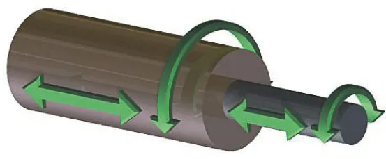
Fig. 2.1: A plain shaft can slide along the common axis inside a plain hole.
A plain hole constrains a shaft of similar size so that the shaft can slide in and out of the hole, and can rotate (Fig. 2.1), but the axis of the shaft and the axis of the hole must remain co-incident.
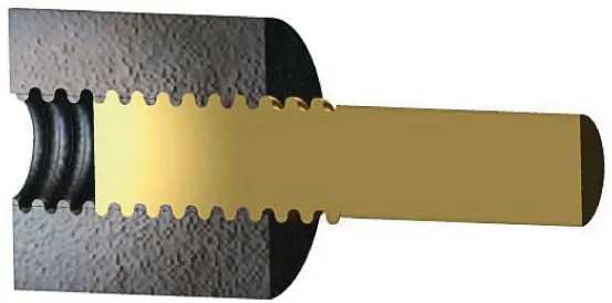
Fig. 2.2: Cross-section of a helically-ridged shaft inside a hole carrying a matching helical groove.
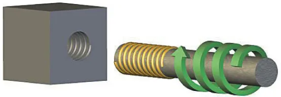
Fig. 2.3: A shaft carrying a helical ridge can only move into or out of a hole carrying a matching helical groove if the shaft rotates.
Creating a uniform helical groove in the wall of the hole, and a matching helical ridge on the shaft (Fig. 2.2), means that if the nut remains stationary, the only way to slide the screw in and out of the hole will be to rotate the shaft (Fig. 2.3). This feature also means that rotating the shaft will force it to move in or out of the nut. Several useful consequences follow from this arrangement.
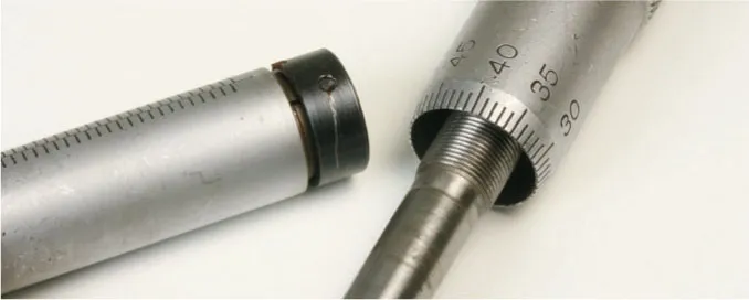
Fig. 2.4: A micrometer makes use of the fact that rotating a shaft with a helical ridge inside a hole with a matching helical groove causes precise movement of the shaft.
Rotating a shaft with a uniform helical ridge in a hole with a mating groove will provide a uniform and predictable linear movement of the shaft for a given rotation, allowing precise control over the movement of the shaft (Fig. 2.4).
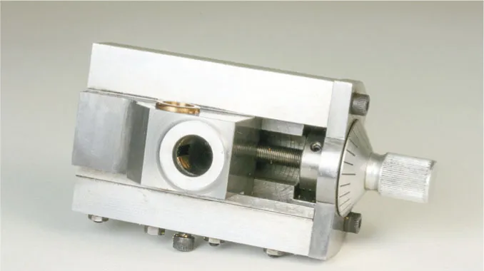
Fig. 2.5: In this boring head, the shaft carries a helical ridge and can rotate but is prevented from moving along its axis. The hole in the slide contains a matching helical groove, so turning the shaft forces the slide to move a distance related to the rotation of the shaft.
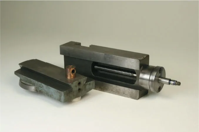
Fig. 2.6: In this topslide, the body contains a hole with a helical groove, and the slide holds a captive shaft with a helical ridge. The body is held stationary in the lathe, so rotating the shaft makes the slide move.
Constraining the shaft so that it can rotate but make no linear movement (like the feedscrew on a lathe cross-slide), and preventing rotation of the hole, will force linear movement of the hole (like the threaded hole or captive nut in the moving part of a cross-slide). This is a widely used principle (Figs 2.5 and 2.6).
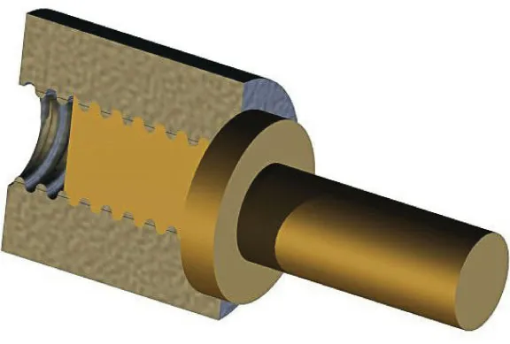
Fig. 2.7: Compression and friction between flange and body and between the helices locks the shaft in the hole.
Rotating the shaft until a flange butts against the material surrounding the hole will tend to lock the shaft and hole in that position because of compression and friction between flange and body, and between the helical ridge and the groove (Fig. 2.7).
These properties make the uniform helix an extraordinarily useful device to connect a shaft and a hole – so useful that it has become a key engineering device and forms the basis of the screw thread in all its forms.
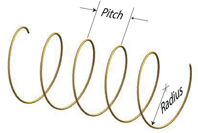
Fig. 2.8: A regular helix has a consistent radius and pitch.
A helix is a curve in three-dimensional space (Fig. 2.8), and a circular helix has the same radius of curvature at all points, making this the most useful form of helix for use with a cylindrical shaft and hole.
The pitch of a helix is the distance between two identically positioned points on adjacent turns of the helix, and a uniform (or ‘regular’) helix has the same pitch between all adjacent turns of the helix.
The helix is a mathematical concept, and is a line with no thickness; so creating a practical helix around a shaft and hole in the real world means creating a ridge around the helix on the shaft, and a matching groove that follows the helix in the hole. The shape of the ridge and groove, and the pitch and diameter of the helix, define the threadform, which is, literally, ‘the form (or shape) of the thread’. The pitch and diameter of the screw thread are the pitch and diameter of the helix.
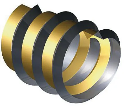
Fig. 2.9: Two intertwined helices. The darker represents the projections above the surface of a shaft, and the lighter represents the groove cut into the shaft.
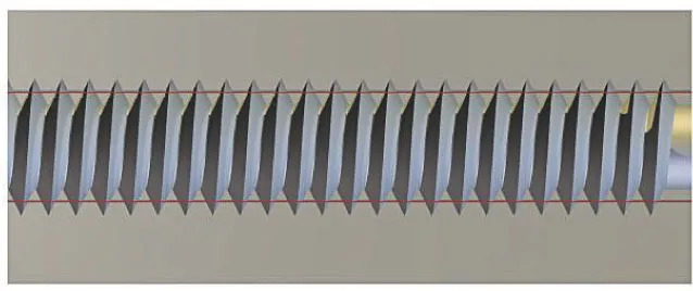
Fig. 2.10: A sectional view of a meshed V-shaped nut and screw. The red lines define the edges of the pitch cylinder pitch.
It would be possible to create a thread by wrapping a wire with a semi-circular section around a shaft (Fig. 2.2) and machining a matching semi-c...
Table of contents
- Cover Page
- Title Page
- Copyright Page
- Contents
- Acknowledgements
- Introduction
- 1 From Beginning to End
- 2 Threadforms
- 3 Thread Calculations
- 4 Measuring Threads
- 5 Using Taps and Dies
- 6 Preparing for Screwcutting in a Lathe
- 7 Screwcutting Tools and Cutting Speeds
- 8 Cutting Threads
- 9 Varying Pitch
- 10 Thread Milling, Grinding and Rolling
- Projects:
- Reference Tables
- Further Information
Frequently asked questions
Yes, you can cancel anytime from the Subscription tab in your account settings on the Perlego website. Your subscription will stay active until the end of your current billing period. Learn how to cancel your subscription
No, books cannot be downloaded as external files, such as PDFs, for use outside of Perlego. However, you can download books within the Perlego app for offline reading on mobile or tablet. Learn how to download books offline
Perlego offers two plans: Essential and Complete
- Essential is ideal for learners and professionals who enjoy exploring a wide range of subjects. Access the Essential Library with 800,000+ trusted titles and best-sellers across business, personal growth, and the humanities. Includes unlimited reading time and Standard Read Aloud voice.
- Complete: Perfect for advanced learners and researchers needing full, unrestricted access. Unlock 1.4M+ books across hundreds of subjects, including academic and specialized titles. The Complete Plan also includes advanced features like Premium Read Aloud and Research Assistant.
We are an online textbook subscription service, where you can get access to an entire online library for less than the price of a single book per month. With over 1 million books across 990+ topics, we’ve got you covered! Learn about our mission
Look out for the read-aloud symbol on your next book to see if you can listen to it. The read-aloud tool reads text aloud for you, highlighting the text as it is being read. You can pause it, speed it up and slow it down. Learn more about Read Aloud
Yes! You can use the Perlego app on both iOS and Android devices to read anytime, anywhere — even offline. Perfect for commutes or when you’re on the go.
Please note we cannot support devices running on iOS 13 and Android 7 or earlier. Learn more about using the app
Please note we cannot support devices running on iOS 13 and Android 7 or earlier. Learn more about using the app
Yes, you can access Screwcutting by Marcus Bowman in PDF and/or ePUB format, as well as other popular books in Technology & Engineering & Engineering General. We have over one million books available in our catalogue for you to explore.