Since the beginning, the development of quadcopters and drones has been strongly influenced by sensors in combination with microprocessors. These flight systems would not be feasible without sensors, because gyros, acceleration sensors and inertial measurement units, for example, are absolutely necessary to make them fly. These are used for axis control. Others, such as the electronic compass, the air pressure sensor or GPS, make control considerably easier for the pilot. Together with sophisticated software, additional sensors such as ultrasonic, infrared or cameras allow additional functions such as automated take-offs and landings, obstacle detection or object tracing. All these sensors and their physical principles are explained in this booklet and their use and possibilities in quadrocopters and drones are discussed.
- 52 pages
- English
- ePUB (mobile friendly)
- Available on iOS & Android
eBook - ePub
Sensors and GPS for Drones and Quadcopters
About this book
Trusted by 375,005 students
Access to over 1.5 million titles for a fair monthly price.
Study more efficiently using our study tools.
Information
1. Introduction and functionality
1.1 Sensors for quadcopters and drones
The name of this model construction division, which was completely new just a few years ago, has developed. At the beginning there was the term 'quadcopter'. Since many model makers also build systems with six or eight propellers, there are also the terms 'hexacopter' and 'octocopter'. These different designs are also referred to with the general term of the multicopter.
The term 'drone' has also been used for these systems since around 2010. This term is originally known for military flight systems. This refers to unmanned flying objects that can fly autonomously via GPS or also remotely. It is important that they are unmanned, i.e. that no pilot is sitting in the cockpit. In principle, this can mean the systems of all possible flight principles, i.e. in addition to quad- and multicopters also fixedwing aircraft, as well as helicopters. In colloquial terms, however, the term drone has now almost become a synonym for quadcopter or general multicopter. This book only deals with this colloquial term drone, i.e. with the quad- or multicopters. The unmanned fixed-wing aircraft are therefore not dealt with here.
The sensors used have also evolved. The first quadcopters only had gyros in two or three axes. This resulted in high demands on the pilot of the drone. The acceleration sensors were added later, the combination allowed an automatic angular control. Then came the compass, the air pressure sensor and the GPS. Today all types and other sensors are used, which greatly simplifies the control of the drones. The sensors are the key for a simple control. The aim of this booklet is to explain their function in context with drones.
1.2 Steering mechanism and technical background
Quadrocopters are aircraft with four propellers. They have the same control capabilities as helicopters. Figure 1 illustrates this. The stick assignment of the remote control, as shown in Figure 2, is most commonly selected. However there are also model pilots who swap the left and right sides.
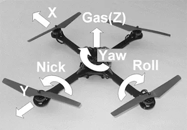
Figure 1: Steering possibilities.
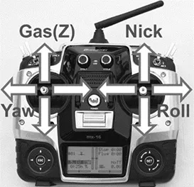
Figure 2: Stick assignment.
‘Nick’ describes the tilting forward and backward. For that purpose, the stick of the remote control needs to be moved upwards (tilting forward) and downwards (tilting backward).
‘Roll’ describes the tilting to the left and right. The stick needs to be moved to the left and the right side.
‘Yaw’ describes the rotation around the vertical axis (z). The left stick needs to be moved to the left (counterclockwise yaw, view from top side) or the right (clockwise yaw, view from top side).
‘Gas’ describes the movement along the vertical axis (z). If the left stick is moved down, it means descent flight, and if the left stick is moved up into the full throttle position, it means climb flight.
1.3 Physical movement
The immediate question is now how a quadrocopter can be controlled physically with the above functions. A helicopter will again serve as a comparison.
‘Nick’ and ‘Roll’ are there realized with a so-called swash plate. This provides at the end an angle-shift of the main rotor force axis to the fuselage. ‘Gas’ is provided by ‘pitching’, which is achieved by changing the pitch of the rotor blades. ‘Yaw’ is realized by a change in speed of the tail rotor. Some models also reach yaw by pitching the tail rotor blades.
Anyone who has ever built and flown helicopters knows that this requires quite a complex mechanism. A hard landing is rarely forgiven: bent rods, ragged ball heads and expensive repairs are the consequence. Many have thus abandoned the model helicopter hobby, the so-called pinnacle of model aircraft.
Quadrocopters, which – as mentioned above – have the same movement possibilities as helicopters, in contrast stand out by virtue of their much simpler and thereby massively less sensitive mechanics: There are four motors, which are rigidly connected with two right- and two left-rotating propellers – and that’s all. Everything else is provided by a little electronic control board or a flight controller. Figure 3 illustrates this.
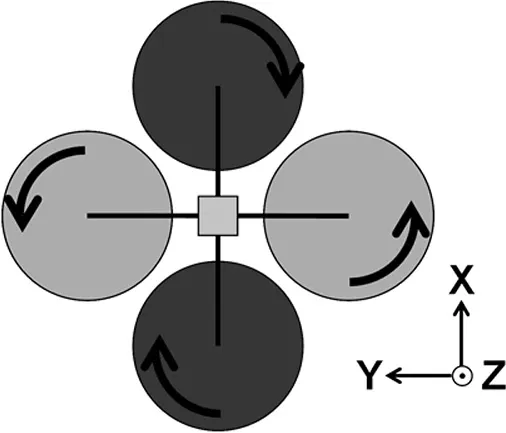
Figure 3: Two left- and right- rotating propellers, view from top side.
‘Nick’ is physically achieved by a change in speed of the upper and lower propeller (see figure 3). To move the quadcopter in the X direction, the lower propeller is turning faster and the upper one slower. Thus, an inclination in the direction of the x-axis is achieved.
‘Roll’ is achieved by a change in speed of the left and right propeller. A movement in the Y direction requires a higher speed of the right and a lower speed of the left propeller.
The main rotor of a helicopter produces a torque about the vertical axis (z) because of its twisting. The tail rotor serves to compensate for that torque. The two right- and left-rotating propellers of the quadrocopter do this job instead. Thus a tail rotor is not needed. ‘Yaw’ is achieved by ensuring that both left and right propellers have a different speed than both upper and lower ones. A counter-clockwise yaw (viewed from above) requires a higher speed of the upper and lower propeller and a lower speed of the left and right one.
A change in ‘Gas’ requires a change in the speed of all propellers together. During the climb flight, all propellers have a higher speed.
As mentioned above, quadrocopters and helicopters are controlled by the same functions and also have the same possibilities of movement – almost. Because of the control over the speed of the propellers it is not possible to fly stably overhead and to ‘mow the lawn’, as some pilots demonstrate with their pitch-controlled helicopters.
Loopings, on the other hand, are also possible with quadcopters, they are flown in the same way as with a wing plane, whereby the gas is slightly removed shortly before the apex and then strongly tightened again for the subsequent stabilization in the hover position. However, this presupposes that the operation allows this, because the sensor support at many systems ensures that the maximum angular position is limited by the software. However, many ready-to-fly quadcopters support automatic loops, which can be triggered by pressing a switch or a button.
1.4 Flight in ‚x’- or ‚+’- configuration
Since a quadrocopter is constructed so perfectly symmetrically, the question of where the front is, is justified. For most systems it is as shown in figure 4. This flight configuration is called the 'x' configuration. So here is not one boom at the front, but the middle between two booms. This configuration is also the standard for a photo flight, because it allows the camera to be mounted facing forwards without the annoying boom and motor / propeller combination. It is then mounted with or without an existing gimbal, a camera holder that can rotate and swivel. In the normal position, it is inclined slightly downwards so that the front propellers do not come into the picture on the left and right ...
Table of contents
- Table of Contents
- 1. Introduction and functionality
- 2. Basic sensors
- 3. GPS
- 4. Other sensors
- 5 Literature
- Copyright
Frequently asked questions
Yes, you can cancel anytime from the Subscription tab in your account settings on the Perlego website. Your subscription will stay active until the end of your current billing period. Learn how to cancel your subscription
No, books cannot be downloaded as external files, such as PDFs, for use outside of Perlego. However, you can download books within the Perlego app for offline reading on mobile or tablet. Learn how to download books offline
Perlego offers two plans: Essential and Complete
- Essential is ideal for learners and professionals who enjoy exploring a wide range of subjects. Access the Essential Library with 800,000+ trusted titles and best-sellers across business, personal growth, and the humanities. Includes unlimited reading time and Standard Read Aloud voice.
- Complete: Perfect for advanced learners and researchers needing full, unrestricted access. Unlock 1.5M+ books across hundreds of subjects, including academic and specialized titles. The Complete Plan also includes advanced features like Premium Read Aloud and Research Assistant.
We are an online textbook subscription service, where you can get access to an entire online library for less than the price of a single book per month. With over 1.5 million books across 990+ topics, we’ve got you covered! Learn about our mission
Look out for the read-aloud symbol on your next book to see if you can listen to it. The read-aloud tool reads text aloud for you, highlighting the text as it is being read. You can pause it, speed it up and slow it down. Learn more about Read Aloud
Yes! You can use the Perlego app on both iOS and Android devices to read anytime, anywhere — even offline. Perfect for commutes or when you’re on the go.
Please note we cannot support devices running on iOS 13 and Android 7 or earlier. Learn more about using the app
Please note we cannot support devices running on iOS 13 and Android 7 or earlier. Learn more about using the app
Yes, you can access Sensors and GPS for Drones and Quadcopters by Roland Büchi in PDF and/or ePUB format, as well as other popular books in Technology & Engineering & Electrical Engineering & Telecommunications. We have over 1.5 million books available in our catalogue for you to explore.