![]()
1
Basic Principles of Intracardiac Echocardiography
Charles Ogdon, MD; Divya Korpu, MD; Sorin C. Danciu, MD, MS
Introduction
The use of echocardiography in cardiology practice dates to the mid-20th century and continues to rapidly evolve. Technologies have expanded from the original “M Mode” to 2D echocardiography, color flow Doppler hemodynamics, 3D processing, and various invasive imaging techniques. Advantages of clinical echocardiography include ease of use, widespread application with diagnostic accuracy, and cost effectiveness. Additionally, invasive modalities such as transesophageal echocardiography (TEE) and intracardiac echocardiography (ICE) have provided enhanced interventional skills and therapeutics.
There has been an exponential increase in the number of percutaneous interventions performed over the last few decades. With significant limitations by use of traditional fluoroscopy and TEE, electrophysiologists have adopted ICE as a primary intraprocedural imaging modality. ICE uses a catheter-tip transducer to generate ultrasound images from within the heart and was first described in the 1980s.1 It allows for improved intracardiac structure visualization with high resolution and real-time imaging. Furthermore, it can be performed by a single proceduralist, does not require a separate invasive procedure with general anesthesia, and minimizes fluoroscopy time. Given these advantages, use of ICE has been incorporated into ablation of cardiac arrhythmias, left atrial appendage occluder devices, atrial septal defect closures, and percutaneous valvular interventions. It is important to have a basic understanding of ultrasound physics and echocardiographic imaging techniques before discussion of detailed clinical applications with ICE.
Basics of Ultrasound
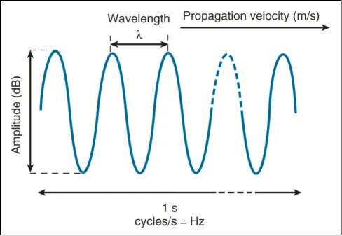
The physical principles of ICE are similar to traditional ultrasound echocardiography. Sound waves are propagating vibrations and are described in terms of frequency (Hz), velocity (m/s), wavelength (mm), and amplitude (dB) (Figure 1.1). The term “ultrasound” refers to frequencies above the human audible threshold (i.e., > 20 kHz).2 Ultrasound waves are generated by piezoelectric crystal transducers. These waves travel through human tissues with varying densities and are reflected back to the transducer as echoes for amplification and image processing. By measuring the delay in echo return, structure location and depth can be translated.
Wavelength is indirectly related to frequency and can be calculated by the equation:
λ = c/f, where c is the speed of sound in soft tissue (~1540 m/s).2
Figure 1.1 Schematic diagram of an ultrasound wave. (Reproduced with permission from Ref. 2.)
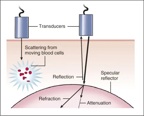
This relationship is important given the trade-off between increased image resolution (high frequency, short wavelength) and image depth (low frequency, longer wavelength). Ultrasound waves also have variable interactions with biologic tissue based on acoustic impedance, reflection, scattering, refraction, and attenuation, which have a large impact on overall image quality and formation (Figure 1.2).2
Acoustic Impedance
Directly related to the density of specific tissue (p) involved and the velocity (c) within that tissue, where Z = pc. This concept of acoustic impedance is the foundation of echocardiographic image formation, with visualized reflections from adjacent tissues with differing acoustic impedance.2
Reflection
Cornerstone of 2D echo image creation with beams perpendicular to tissue allowing greatest reflection.
Refraction
Based on acoustic impedance, sounds waves can be deflected, which can result in image artifacts.
Scattering
Ultrasound signals are radiated in different directions after interaction with small structures (i.e., red blood cells). Doppler echocardiography is based on this principle by measuring the change in frequency.
Attenuation
Loss of ultrasound signal due to energy being absorbed by tissue. Directly related to frequency.
Figure 1.2 Diagram of ultrasound wave interaction with tissue. (Reproduced with permission from Ref. 2.)
Imaging Techniques Used in ICE
2D Echo
2D echocardiography generates pulses of sound waves that are received over multiple scan lines in real time. By use of parallel processing, up to 4 scan lines are displayed simultaneously to increase frame rates. This is the primary modality utilized in ICE for real-time intracardiac structure and anatomic visualization.
3D Echo
3D echocardiography allows visualization of all 3 spatial dimensions by using a complex multiarray transducer. Structures can be visualized in real time and in any orientation, but the modality is limited by temporal resolution.
Doppler Echocardiography
Doppler echocardiography is based on the principle that ultrasound waves returning from a moving red blood cell causes a microscopic change in frequency, allowing for quantification of blood velocity. By using spectral analysis, these frequencies can be displayed to measure direction and speed of flow. This Doppler signal can be displayed in a few different ways, each with its own advantages and disadvantages.
Continuous Wave Doppler
In continuous wave Doppler, ultrasound signals are sent and received by 2 separate transducer crystals to allow measurement of highest velocity of blood flow. It is limited in velocity localization.
Pulsed Wave Doppler
A single transducer crystal sends episodic pulses and waits for return before the next pulse. This modality allows for specific velocity localization, but it is limited by inability to display high velocities.
Color Flow Doppler
Color flow Doppler measures the shift change between 2 pulses to determine blood flow moving toward transducer (red) or away from transducer (blue). Essential technique for evaluation of valvular hemodynamics. Limited by aliasing and lower frame rates.
Types of Intracardiac Echocardiography Systems
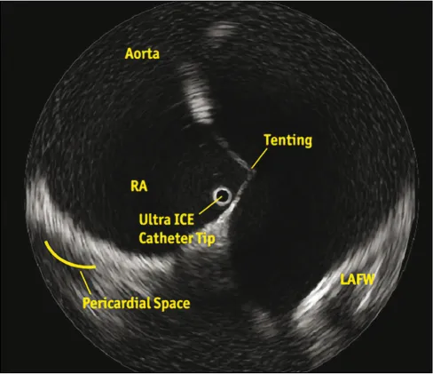
A mechanical or rotational system uses a single rotational piezoelectric crystal mounted on the tip of a 6- to 10-Fr catheter. It produces a 360-degree cross-sectional image perpendicular to the long axis of the catheter (Figure 1.3). It operates at a higher frequency (10–20 MHz), which limits the depth of tissue penetration, making it useful for near-field imaging up to 5 cm. Limited by its stiffness,3,4 it is mostly used to assess coronary vessel/lumen diameter, lesion length, and plaque buildup, and it helps determine proper placement and deployment of coronary stents. In electrophysiology, these catheters are used to directly visualize left atrial anatomy, aid transseptal puncture, verify tip-tissue contact during ablation, and monitor for early signs of thrombus formation or stenosis.
Figure 1.3 Boston Scientific’s UltraICE rotational catheter provides a 360-degree panoramic view perpendicular to the long axis of the catheter. It is positioned in the right atrium adjacent to the fossa ovalis to aid transseptal puncture.
A phased-array catheter system uses a 64-piezoelectric element linear array transducer mounted on the tip of an 8- to 10-Fr catheter. It produces a 90-degree...