This book is a concise, practical treatise for the student or experienced professional aircraft designer. This first volume comprises key fundamental subjects for aerodynamic performance analysis: the basics of flight mechanics bridging both engineering and piloting perspectives, propulsion system performance attributes, practical drag prediction methods, aircraft "up and away" flight performance, and aircraft mission performance. This book may serve as a textbook for an undergraduate aircraft performance course or as a reference for the classically trained practicing engineer.
- 274 pages
- English
- ePUB (mobile friendly)
- Available on iOS & Android
eBook - ePub
Aircraft Performance and Sizing, Volume II
About this book
Trusted by 375,005 students
Access to over 1.5 million titles for a fair monthly price.
Study more efficiently using our study tools.
Information
CHAPTER 1
__________________________
SYSTEMS ENGINEERING AND THE DESIGN PROCESS
Aircraft are complex systems. It takes a team of experts, not an individual, to design an aircraft. Thus, considerable attention needs to be paid when assembling, managing, and leading a technical team. The U.S. government, led by the military, has identified many best practices and established clear project management guidelines for aerospace systems design. These are documented in MIL STD-881C.1
Typically, a pressing business or military need defines the top-level concept. A very small number of engineers, business executives, or military leaders conceive both the basic vehicle configuration and its overall concept of operations. By the nature of this conceptualization process, a vehicle configuration developed at program inception lacks stringent technical rigor. The design is either cartooned with no numerical analysis, or, at best, is supported by some back-of-the-envelope calculations. The decisions made or implied during this phase of the program have significant future consequences because they define so many key attributes: for example, the choice of principal business partners, the choice of materials, the number of engines, or the use or disuse of specific technologies.
1.1 THE SYSTEMS ENGINEERING VEE—A PLAN FOR SUCCESS
The systems engineering process uses an interdisciplinary approach to conceptualize and build complex products.2 As practitioners of systems engineering, systems engineers focus “on defining customer needs, … [and] documenting requirements.”3 The systems engineering process should coordinate “design synthesis and system validation while considering the complete problem.” The role of systems engineering should be to integrate “all the disciplines and specialty groups into a team effort forming a structured development process that proceeds from concept to production to operation.”4
Systems engineering uses a formal decision-making review process to provide external visibility to the design activity, manage project scope, and establish basic requirements. Basically, systems engineers force other engineers, who prefer to be hermits, to share their incomplete designs with one another at regularly scheduled meetings. The idea behind these formal gate review meetings is to encourage stakeholder involvement, dialog, and participation. A schematic of the design steps and the gate review meetings may be seen in Figure 1.1.4
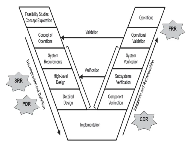
Figure 1.1. Systems engineering “Vee.” FRR, flight readiness review; SRR, systems requirement review; PDR, preliminary design review; CDR, critical readiness review.
Traditional systems engineering, as articulated by Defense Acquisition Order DoD5000.023 and MIL-STD 499A,5 breaks down the aircraft design process into several phases from inception through first flight:
1. A Systems Requirements Definition (SRD) phase, leading to a Systems Requirements Review (SRR);
2. A Preliminary Design (PD) phase, leading to a Preliminary Design Review (PDR);
3. A Detail Design phase, leading to a Critical Design Review (CDR), and
4. An assembly and ground test phase that supports a Flight Readiness Review (FRR).
Technical reviews allow the government an overview of the evolving system design and an opportunity to evaluate its capability to satisfy performance requirements. The objective of these reviews is to search out design weaknesses, faulty designs that preclude certification (on a commercial program), or designs which may be cost drivers (on a military program). Engineers write technical status reports to support design reviews. Managers then use these reports to identify, clarify, and mitigate potential items of concern before the formal design review meeting.
It is essential that customer representatives participate in formal design reviews. Typically, the technical review will proceed as a series of formal presentations by the contractor’s design team. Presentations should begin with a brief overview of the overall program (scope, deliverables, and milestone schedules) to set the stage for the design briefs. Presentations should contain an overall systems perspective reflecting the major subsystems and how they interface to comprise the total system.
The symmetrical Systems Engineering Vee (see Figure 1.1) ties the system specification, generated by tasks found on the left-hand side of the diagram to the system verification results, performed by tasks found on the right-hand side of the vee. Ideally, requirements developed in the early phase of the program drive the validation process performed in later phases. In this structure, parts design is performed at the bottom of the vee. The steps preceding detail design level serve to decompose requirements; steps after detail design serve to verify performance. SRR and PDR occur on the left-hand side, and the bottom of the systems engineering vee comprises the development time between PDR and CDR.
It is widely believed that engineering design determines 80 percent of a product’s cost.6 Unit costs are materially impacted by poor conceptual design that requires revision and change during detail design or development (delaying product delivery or producing a product that does not meet requirements). Poor concept design gives us products that fundamentally do not meet expectations. Poor detail design results in products where required parts tolerances are too tight for economical construction, assembly techniques are needlessly expensive or unreliable, or products where parts fail needlessly in service. To build a successful product requires more than serendipity or unharnessed technical expertise; it requires a structured process to ensure that small technical missteps do not grow into program-threatening problems.
1.2 CONCEPTUAL DESIGN
During the conceptual design phase, the technical team should be small and nimble. In practice, supply chain considerations have a driving influence at this phase of design because the industry is not vertically integrated. A new aircraft design is the product of a partnership between airframe prime (e.g., a Boeing), a propulsion house (e.g., a Pratt & Whitney), and principal subsystems contractors (e.g., a Honeywell—for the landing gear and brakes). Often, a large team is required to formalize requirements between the primary integrator and its major subcontractors. This is necessary because the technical team cannot acquire necessary data without negotiating formal contracts that establish joint fiduciary responsibilities and establish intellectual property rights. If a company like Boeing is going to build a new airframe around Pratt & Whitney’s new engine, neither technical team can operate in a vacuum without access to the other’s trade secret data.
The roles and responsibilities of the various members of the program team are defined by the work breakdown structure (WBS).1 When you express the WBS in graphical form, you can see the functional decomposition of the project (see Figure 1.2). Each item on the WBS (box element on the functional decomposition tree) may have a different lead vendor. For example, a Boeing military aircraft (system integrator) might have a Raytheon fire-control system. In turn, differing Raytheon divisions might have leadership on the detection radar system and the missile guidance system. Raytheon might further subcontract the tracking optics to a sub-subcontractor.
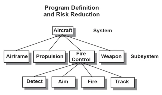
Figure 1.2. Example functional decomposition tree.
Unfortunately, this subcontracting process limits flexibility to implement significant changes in the overall design configuration; the result is that key aircraft design decisions, such as the number of engines and basic engine size, are typically frozen prior to SRR.
At the SRR level, systems engineering seeks to formalize concrete, verifiable requirements that define what the final product will be able to do but not how the system will do it. Thus, the purpose of an SRR is to balance customer desires and stakeholder needs against public policy (e.g., regulatory compliance with the Federal Aviation Administration (FAA)) and/or military standards as well as practical constraints.
Once you pass SRR, you transcribe the agreed upon requirements into a System Requirements Document (SRD). In addition, you publish documents like a System Verification Plan (SVP) and System Acceptance Plan (SAP). These procedural guides describe the steps required to demonstrate compliance with these requirements.
Requirements define “what, how well, and under what conditions a product will achieve a given purpose.”7 The baseline SRD should describe the system in both a qualitative/conceptual and a quantitative/detailed manner. The systems engineering team should encourage input from all stakeholders, including managers, technical staff, and operational staff, and the requirements plan should consider and reflect the complete life cycle (system development, deployment, training, transition, operations and maintenance, upgrades, and retirement) of the proposed system.
An SRR briefing3 should address:
• System requirements and capabilities: Demonstrate that the system specification is complete; that the nonnegotiable design requirements have been identified; and that the design team understands the product from an operational, system and technical perspective.
◦ Explicit requirements: These are technical requirements derived from the stated mission requirements: How much payload? How far? How fast? How economical? Out of what runway?
◦ Implicit requirements: These are engineering requirements inherent to the vehicle class (e.g., the regulations found within 14 CFR 25).
• Test, evaluation, and certification of product: Identify the role of modeling and simulation (M&S) in testing; demonstrate that airworthiness criteria are understood and reflected in the specification; document the requirement verification methodology with the type of analyses, tests, inspection, or demonstrations planned; define the roles of all certifying agencies in the forward project plan
• Engineering processes, control, and analysis: Establish measures of effectiveness (MOEs) (these are the numbers that define the value of the product—for example: per-seat-fuel-consumption over a mission plan); measures of performance (MOPs) (these are the numbers that define compliance with the key constraints—for example, takeoff runway length); key performance parameters (KPPs) (these are other useful numbers, but those that only indirectly, rather than directly, impact the requirement or constraints—for example, stall speed).
• Program Master Schedule, earned value and cost: The review should include an Integrated Master Plan (IMP) and Integrated Master Schedule (IMS) ...
Table of contents
- Cover
- Half Title Page
- Title Page
- Copyright Page
- Contents
- LIST OF FIGURES
- LIST OF TABLES
- ACKNOWLEDGMENTS
- CHAPTER 1 SYSTEMS ENGINEERING AND THE DESIGN PROCESS
- CHAPTER 2 WEIGHT AND VOLUME ESTIMATION
- CHAPTER 3 STABILITY AND CONTROLLABILITY
- CHAPTER 4 FIELD PERFORMANCE PRINCIPLES
- CHAPTER 5 AERODYNAMIC DESIGN OF WINGS
- CHAPTER 6 AIRCRAFT SIZING AND SYNTHESIS—PUTTING IT ALL TOGETHER
- INDEX
Frequently asked questions
Yes, you can cancel anytime from the Subscription tab in your account settings on the Perlego website. Your subscription will stay active until the end of your current billing period. Learn how to cancel your subscription
No, books cannot be downloaded as external files, such as PDFs, for use outside of Perlego. However, you can download books within the Perlego app for offline reading on mobile or tablet. Learn how to download books offline
Perlego offers two plans: Essential and Complete
- Essential is ideal for learners and professionals who enjoy exploring a wide range of subjects. Access the Essential Library with 800,000+ trusted titles and best-sellers across business, personal growth, and the humanities. Includes unlimited reading time and Standard Read Aloud voice.
- Complete: Perfect for advanced learners and researchers needing full, unrestricted access. Unlock 1.5M+ books across hundreds of subjects, including academic and specialized titles. The Complete Plan also includes advanced features like Premium Read Aloud and Research Assistant.
We are an online textbook subscription service, where you can get access to an entire online library for less than the price of a single book per month. With over 1.5 million books across 990+ topics, we’ve got you covered! Learn about our mission
Look out for the read-aloud symbol on your next book to see if you can listen to it. The read-aloud tool reads text aloud for you, highlighting the text as it is being read. You can pause it, speed it up and slow it down. Learn more about Read Aloud
Yes! You can use the Perlego app on both iOS and Android devices to read anytime, anywhere — even offline. Perfect for commutes or when you’re on the go.
Please note we cannot support devices running on iOS 13 and Android 7 or earlier. Learn more about using the app
Please note we cannot support devices running on iOS 13 and Android 7 or earlier. Learn more about using the app
Yes, you can access Aircraft Performance and Sizing, Volume II by Timothy Takahashi in PDF and/or ePUB format, as well as other popular books in Technology & Engineering & Mechanical Engineering. We have over 1.5 million books available in our catalogue for you to explore.