The ultimate power-packed crash course in building Arduino-based projects in just 10 days!About This Book• A carefully designed 10-day crash course, covering major project/device types, with 20+ unique hands-on examples• Get easy-to-understand explanations of basic electronics fundamentals and commonly used C sketch functions• This step-by-step guide with 90+ diagrams and 50+ important tips will help you become completely self-reliant and confidentWho This Book Is ForThis book is a beginner's crash course for professionals, hobbyists, and students who are tech savvy, have a basic level of C programming knowledge, and basic familiarity with electronics, be it for embedded systems or the Internet of Things.What You Will Learn• Write Arduino sketches and understand the fundamentals of building prototype circuits using basic electronic components, such as resistors, transistors, and diodes• Build simple, compound, and standalone devices with auxiliary storage (SD card), a DC battery, and AC power supplies• Deal with basic sensors and interface sensor modules by using sensor datasheets• Discover the fundamental techniques of prototyping with actuators• Build remote-controlled devices with infrared (IR), radio frequency (RF), and telephony with GSM• Learn IoT edge device prototyping (using ESP8266) and IoT cloud configurationIn DetailThis book is a quick, 10-day crash course that will help you become well acquainted with the Arduino platform. The primary focus is to empower you to use the Arduino platform by applying basic fundamental principles. You will be able to apply these principles to build almost any type of physical device.The projects you will work through in this book are self-contained micro-controller projects, interfacing with single peripheral devices (such as sensors), building compound devices (multiple devices in a single setup), prototyping standalone devices (powered from independent power sources), working with actuators (such as DC motors), interfacing with an AC-powered device, wireless devices (with Infrared, Radio Frequency and GSM techniques), and finally implementing the Internet of Things (using the ESP8266 series Wi-Fi chip with an IoT cloud platform).The first half of the book focuses on fundamental techniques and building basic types of device, and the final few chapters will show you how to prototype wireless devices. By the end of this book, you will have become acquainted with the fundamental principles in a pragmatic and scientific manner. You will also be confident enough to take up new device prototyping challenges. Style and approachThis step-by- step guide will serve as a quick, 10-day crash course to help you become well acquainted with the Arduino platform.

- 288 pages
- English
- ePUB (mobile friendly)
- Available on iOS & Android
eBook - ePub
Learn Arduino Prototyping in 10 days
About this book
Trusted by 375,005 students
Access to over 1.5 million titles for a fair monthly price.
Study more efficiently using our study tools.
Information
Day 1 - Building a Simple Prototype
"A journey of thousand miles must begin with a single step."
-Lao-tsu
We will start this chapter by learning to build our first electronic circuit around the Arduino Uno board. This will be our first hardware-software integrated prototype. Two examples have been chosen for this chapter. The first example is a series of three external red Light Emitting Diodes (LEDs). We will write an Arduino sketch that will blink the three LEDs, one at a time, in a cyclic fashion. The second example is using a Piezo Buzzer. We will learn to write a sketch to play a musical tune using the Buzzer.
The reason for starting off with these basic examples is to understand how to build a prototype using the Arduino platform. And what better way could there be than to show some light (using the LEDs) and make some sound (using the Buzzer)!
After reading through this chapter, the reader will understand the fundamentals of using basic electronic components such as resistors, transistors, and diodes.
Things you will learn in this chapter:
- Use of resistors to reduce current flow
- Ohm's Law based resistance calculation
- Introduction to the breadboard
- Blinking multiple external LEDs
- Concept of common grounding
- Making sound with Buzzers
- Using transistors for switching
- Using rectifier diodes for preventing flow of current
The three LED project
If you are beginning your journey with micro controller-based prototyping, read on carefully. This discourse will empower you to jump start using the Arduino platform for rapid hardware software prototyping. It should be treated as a quick starter guide for using certain electronic components. However, for advanced electronics usage and calculations; an electronics engineering book must be referred to:
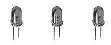
Figure 1: The three LED project
Before we start with the three LED project, the following section will provide a quick summary of why resistors will be used in this project.
Rationale for using a resistor
Resistors are commonly used to reduce the amount of current flowing from the source to the destination. To draw up an analogy, it is like squeezing a water supply tube at a particular point thus reducing the flow of water. Similarly, by placing a resistor across a piece of wire, the flow of current gets reduced.
Use a resistor to reduce the flow of the current in a circuit, in order to protect a delicate electronic component that cannot tolerate high currents.
The rule of thumb is to apply a resistor of an appropriate value, in series just before a delicate electronic component that cannot withstand too much current, for example an LED. We will look at an example of this fundamental concept in the following hands-on activity for blinking the three external LEDs in a cyclic fashion.
The two ends of a resistor do not have any polarity. A resistor can be placed in any direction in a circuit.
First things first, to begin with, we must understand why using a 220 Ohms resistor is necessary. Typically, a red LED is rated to work at 20 mA and has a voltage drop of 1.4 volts across it.
Keep the classical Ohm's Law formula, shown in the following, in mind while trying to calculate the adequate value of the resistance to be employed.
Resistance = Voltage / Current
Resistance = Voltage / Current
When receiving current from a 50mA source (Arduino pins in this case), the current needs to be reduced before it is allowed to flow through the LED. If the amount of current is not reduced then the LED will burn out eventually.
Ohms law is used, as described in the following, to determine the required value of the resistor:
Resistance = (Supply voltage - LED voltage drop) / Current
= (5 volts - 1.4 volts) / 0.020 amps
= 3.6 volts / 0.020 amps
= 180 Ohms
~ 220 Ohms (nearest standard resistor value)
Although beyond the scope of this book, you will have to get used to determining the value of a resistor by looking at the color bands. In the beginning, when you work out of a starter kit, everything will be fine for a few weeks as all the resistors will come labelled properly.
However, after a few months, as you start building more prototypes, it is very likely that you will lose track of which one is which. In order to avoid any confusion, additional reading is suggested online, for decoding the resistor color bands by visual inspection.
However, after a few months, as you start building more prototypes, it is very likely that you will lose track of which one is which. In order to avoid any confusion, additional reading is suggested online, for decoding the resistor color bands by visual inspection.
For this project, the following parts will be required:
- Arduino Uno R3
- USB connector
- 1 breadboard
- 3 red LEDs
- 3 pieces 220 ohms resistors
- Some male-to-male jumper wires
Once all the required parts are available, go ahead and assemble them as shown in the following breadboard diagram:
In the diagram, you will notice the logo fritzing mentioned in the image. The fritzing software is an open source program used for creating circuit diagrams. While you are mastering the basics outlined in this book and starting your journey with Arduino, fritzing will help you to quickly draw your circuit diagrams.
Throughout this book, the basic breadboard diagrams have been created using fritzing. However, some additional labeling has been done outside fritzing. Overall, using fritzing is highly recommended for your device prototyping journey:
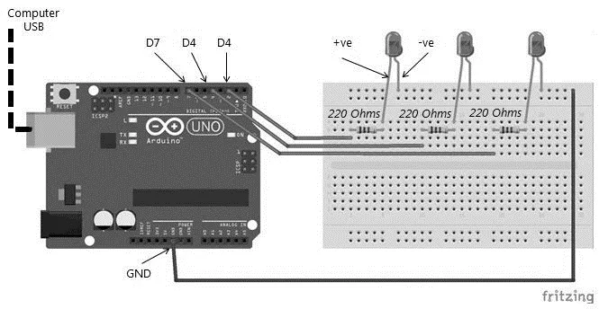
Figure 2: Wiring of the three LED project
The connection details between the Arduino Uno board and the three LEDs are provided in the following table for reference:
| Arduino Uno pin | LED pin(s) |
| Digital pin 2 | +ve (longer) leg of the 1st LED |
| Digital pin 4 | +ve (longer) leg of the 2nd LED |
| Digital pin 7 | +ve (longer) leg of the 3rd LED |
| GND | -ve (shorter) legs of the 3 LEDs |
Table 1: Arduino to LED pin mapping
Let us understand the breadboard circuit connections in detail. When connecting LEDs, the thumb rule is to connect the longer leg of the LED to the positive terminal of the power source. The longer leg of an LED is the positive terminal of the LED. In our case, we are going to connect the positive terminals of the LEDs to digital pins of the Arduino board.
The digital pins of the Arduino board will supply the required current to make the LEDs glow. The shorter leg of an LED is the negative terminal. The negative terminal is connected to the ground. In our case, you will notice that the shorter legs of the three LEDs have been connected to the GND (ground) pin of the Arduino board.
Note that all the shorter legs or the negative terminals of the three LEDs are connected to Arduino's GND (ground) pin via a common wire. This concept is referred to as common grounding. The basic idea is that all components in a circuit should have a common ground or reference for operating correctly. This is an important concept and will be very useful when you start building more complex prototypes with independent power sources. An advanced example of common grounding will be presented in the Chapter 7, Day 5 - Using Actuators.
After assembling the circuit, load the following sketch into the Arduino Uno board. It is advisable not to connect any wires to the Rx (pin D0) and Tx (pin D1) pins of the Arduino board while loading the sketch.
Do not connect anything to pins 0 (Rx) and 1 (Tx) while loading the sketch. This is because these two pins are internally used as the hardware serial lines while the sketch gets loaded from the computer's USB port to Arduino's memory. For the scope of this book, this is the basic precaution that must be taken while loading sketches. Hardware serial communication is the transfer of data between the computer and the Arduino board via the USB ports. Serial communication has been explained in greater detail in Chapter 11, Day 9 - Long Range Wireless Communications.
Go ahead and load the following C sketch. This code may be freely downloaded from the GitHub location mentioned in the Chapter 1, Boot Camp of this book.
 // Step-1: No variables are used in this sketch

//**********************************************************/
// Step-2: INITIALIZE I/O PARAMETERS
//**********************************************************/
void setup()
{
 // initialize digital pins as an output.
 pinMode(2, OUTPUT);
 pinMode(4, OUTPUT);
 pinMode(7, OUTPUT);

}
//**********************************************************/
// Step-3: MAIN PROGRAM
//**********************************************************/
// the loop function runs over and over again forever
void loop()
{...
Table of contents
- Title Page
- Copyright
- Credits
- About the Author
- About the Reviewers
- www.PacktPub.com
- Customer Feedback
- Preface
- Boot Camp
- The Arduino Platform
- Day 1 - Building a Simple Prototype
- Day 2 - Interfacing with Sensors
- Day 3 - Building a Compound Device
- Day 4 - Building a Standalone Device
- Day 5 - Using Actuators
- Day 6 - Using AC Powered Components
- Day 7 - The World of Transmitters, Receivers, and Transceivers
- Day 8 - Short Range Wireless Communications
- Day 9 - Long-Range Wireless Communications
- Day 10 - The Internet of Things
Frequently asked questions
Yes, you can cancel anytime from the Subscription tab in your account settings on the Perlego website. Your subscription will stay active until the end of your current billing period. Learn how to cancel your subscription
No, books cannot be downloaded as external files, such as PDFs, for use outside of Perlego. However, you can download books within the Perlego app for offline reading on mobile or tablet. Learn how to download books offline
Perlego offers two plans: Essential and Complete
- Essential is ideal for learners and professionals who enjoy exploring a wide range of subjects. Access the Essential Library with 800,000+ trusted titles and best-sellers across business, personal growth, and the humanities. Includes unlimited reading time and Standard Read Aloud voice.
- Complete: Perfect for advanced learners and researchers needing full, unrestricted access. Unlock 1.5M+ books across hundreds of subjects, including academic and specialized titles. The Complete Plan also includes advanced features like Premium Read Aloud and Research Assistant.
We are an online textbook subscription service, where you can get access to an entire online library for less than the price of a single book per month. With over 1.5 million books across 990+ topics, we’ve got you covered! Learn about our mission
Look out for the read-aloud symbol on your next book to see if you can listen to it. The read-aloud tool reads text aloud for you, highlighting the text as it is being read. You can pause it, speed it up and slow it down. Learn more about Read Aloud
Yes! You can use the Perlego app on both iOS and Android devices to read anytime, anywhere — even offline. Perfect for commutes or when you’re on the go.
Please note we cannot support devices running on iOS 13 and Android 7 or earlier. Learn more about using the app
Please note we cannot support devices running on iOS 13 and Android 7 or earlier. Learn more about using the app
Yes, you can access Learn Arduino Prototyping in 10 days by Kallol Bosu Roy Choudhuri in PDF and/or ePUB format, as well as other popular books in Computer Science & Hardware. We have over 1.5 million books available in our catalogue for you to explore.