This book presents all information necessary to understand the functioning of a slurry loop reactor for the polymerisation of ethylene into high density polyethylene, and to operate it accordingly. All discussions are based on experimental data from the operation of full scale commercial loop reactors.
Methods for off-line modelling and scaling-up from lab to full scale are included, as well as the answers to important questions on the running of two loop reactors in series.
Building knowledge from full scale industrial experience. This highly accessible book makes one understand the functioning of slurry loop reactors for the polymerisation of ethylene, and how to operate them.
Its methods include off-line modelling, scaling-up and running reactors in series. It is inspiring for all production and process engineers, showing, for the first time, how with full scale reactor data the link is made between firm basic theory and the most practical operating guidelines.
- 206 pages
- English
- ePUB (mobile friendly)
- Available on iOS & Android
eBook - ePub
About this book
Trusted by 375,005 students
Access to over 1.5 million titles for a fair monthly price.
Study more efficiently using our study tools.
Information
1 Introduction to the Slurry Loop Process
The polymerisation products of ethylene are among the largest commodity plastics. Low density polyethylene (LDPE) is a highly branched polymer, generated from the monomer at conditions of extremely great pressure and high temperature. High density polyethylene (HDPE) is a linear polymer, and is obtained by catalysis, at moderate pressures and temperatures. The two types of polyethylene are so different in properties that they can hardly be said to be competitors.
Two main processes are known to produce HDPE. In the gas phase process, the polymer particles are formed on catalyst particles that are fluidized in a fluidized bed reactor by a gas stream carrying the monomer. In the slurry loop process the polymer grows on catalyst particles that are suspended in a liquid, wherein the monomer is dissolved, thus forming a slurry that is circulated in a recycle tubular reactor, commonly called loop reactor.
The slurry loop reactor is a long tube, about 600 mm in diameter and a few hundred metres long, of which the ends are connected to make it one closed loop. Its volume is of the order of 100 m3. It is totally filled with the slurry, which is circulated through the loop by one single circulation pump. The larger part of the reactor consists of an even number of vertical tube sections, or legs, connected by short horizontal elbows at the top and the bottom.
The outer aspect of the reactor is that of a tubular reactor, one of the two main model reactors known in chemical reactor engineering, where the reagents are fed at one side of the tube and leave it at the other end. However, since the loop is closed, and the reactor contents are circulated through the loop at a high speed, the behaviour of the reactor is very close to that of the continuous stirred tank reactor, that other model known from reactor engineering textbooks.
Actually, the loop reactor can be regarded as a stirred tank, where the circulation pump has taken over the role of the agitator, and where the vessel has been lengthened to obtain more external cooling surface, and a higher production capacity. Indeed, the heat of reaction of the polymerisation of ethylene is quite high1, and the cooling surface of the reactor is one of the limiting factors to its production capacity. Since a conventional vessel is rather spherical, the ratio of its external surface to its volume is inversely proportional to its diameter. In a loop reactor, the cooling of the reactor contents is effected by cooling water flowing through a cooling jacket, concentric with the tube, and so its external surface is simply proportional to its volume. When the reactor tube is made longer, both volume and cooling surface are increased to the same degree. Due to the fact that the slurry and the cooling water are flowing at very high speeds, high heat transfer coefficients are obtained at both sides of the reactor wall.
dp n="14" folio="2" ?
Three families of catalysts are used in the slurry loop process. They yield polymers of different molecular weight distributions (MWD), and thus allow to produce a very broad range of high density polyethylenes, of which many specific grades are used for specific applications. The reaction mechanisms of the three catalyst families are different, because their active species, that provoke the polymerisation reaction, are different. The active chemical of the chromium oxide catalyst is chromium(VI) oxide stabilised on a silica particle. The resulting MWD is very broad. The Ziegler–Natta catalyst is using a complex of TiCl4 in an environment of MgCl2. The resulting MWD is more narrow. The metallocene catalyst, where a Zr-metallocene group is the active chemical, produces the most narrow MWD. A chromium(VI) oxide catalyst cannot be realised without a silica support, but also the two other catalysts are most often supported on silica particles to facilitate their handling and feeding to the reactor. The size of those silica particles is of the order of 100 µm.
The catalysts are very sensitive to poisoning, especially by moisture. That is why every feed stream to the reactor is purified in an extensive purification section, where, on a series of adsorber beds, the impurity levels are reduced to the order of 0.1 ppm.
The best way to explain how the reactor functions, is by telling how it is started up. In a first step, the loop reactor is filled with the diluent. That is a liquid wherein the reaction ingredients are dissolved, but wherein the solubility of the polymer should be minimal. The most common diluent is isobutane, and also propane is used. The diluent is in the liquid state at the prevailing reactor conditions, viz. temperatures around 100 °C, and pressures around 40 barg.
The reactor is one stage in a greater loop described by this diluent in its course through the process, Figure 1.1, where it is passing a purification step before being fed to the reactor, is flashed off upon leaving the reactor, compressed and condensed, purified in the recovery and purification sections, and finally recycled to the reactor. By the filling of the reactor is meant that this circulation of diluent through the process is set up, and that the diluent in the reactor is at the operating temperature and pressure.
Then the required concentrations of monomer, and, if necessary, comonomer and hydrogen are established in the loop reactor. The condensed liquid, entering the recovery section, will then contain, besides the diluent, also concentrations of ethylene, comonomer and hydrogen. This stream is split up in its components in the recovery section by distillation, as far as is necessary to purify them and control their quantities that are all recycled to the reactor. Only two small purge streams, of lights and heavies, are taken off in the recovery section, which means that most of the liquid is recycled.
The reaction is started by the feeding of the catalyst. Polymer will be formed on the catalyst particles, and so a polymer-diluent slurry will be established. The thickening slurry is allowed to reach its steady state concentration, at some 20 vol%. This concentration is controlled by the feed flow of the recycled diluent, and by the number of settling legs in service.
The settling legs are vertical tubes suspended to the bottom of the reactor, wherein the slurry is allowed to settle and reach a higher concentration of solids. Small quantities
of concentrated slurry are released from each settling leg to the flash tank at regular intervals. The thus effected thickening of the slurry reaching the flash tank is saving capacity and energy in the recovery section.
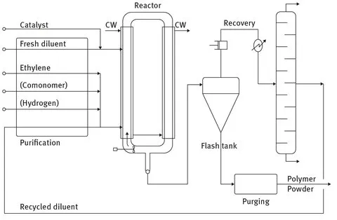
Fig. 1.1. Simplified flow sheet of the HDPE slurry loop process.
The flash tank is maintained at a much lower pressure than the loop reactor, so most of the (hydrocarbon) liquid is flashed off there, and leaves the flash tank by the top outlet, towards the recovery section. The polymer powder is collected at the bottom of the flash tank, and purged from hydrocarbons in a powder purging step. From there it is transferred to the extruder building and pelletised.
2 The Loop Reactor Circulation Pump Power
The first concern of a young operating team, running a new slurry loop reactor, is to keep that reactor running!
When they are given a safe set of reactor conditions, and a known catalyst is fed at a moderate rate, they can maintain an accordingly moderate production rate, without much knowledge of reaction kinetics or catalyst behaviour. It is much more important to them to master the hydrodynamics of the reactor. The slurry therein is circulated at a high speed through the loop by a single axial pump. If that pump fails, the slurry will lose its velocity very fast and, within a few minutes’ time, the polymer powder will settle in the bottom of the reactor as pillar-shaped lumps. There is no other way out then than to open the reactor and clean it, which operation takes at least a week, and is expensive and hazardous.
This trouble can be avoided by a good understanding of the reactor circulation pump behaviour and careful monitoring of the reactor pump power consumption.
2.1 Reactor Pump Circulating Pure Liquid
When starting up the reactor, before reagents are fed, the reactor pump will circulate a pure diluent liquid for some time, to allow to establish the required reactor temperature. The pump power consumed in these circumstances, at a certain temperature, is an interesting data, to be kept as a reference to judge the pump’s future behaviour.
In general, the power consumed by a pump is the energy per unit time required to transfer a liquid from a point 1 to a point 2. It is given by Bernoulli’s equation2. Four different resistances to flow between points 1 and 2 must be dealt with, viz. a difference in height, a difference in pressure, a difference in velocity, and the friction resistances from the pipe wall and in valves and fittings along the trajectory. When expressing these resistances as an energy to be supplied per unit mass of the pumped liquid, Bernoulli’s equation...
Table of contents
- Also of Interest
- Title Page
- Copyright Page
- Preface
- Table of Contents
- 1 Introduction to the Slurry Loop Process
- 2 The Loop Reactor Circulation Pump Power
- 3 The Functioning of the Settling Legs
- 4 The Settling of the Polymer in the Settling Legs
- 5 Catalyst Activity and Productivity
- 6 The 1/1 Hypothesis
- 7 Catalyst Residence Time Distribution
- 8 Catalyst Activity Profiles from Full Scale Loop Data
- 9 Conversions of the Reactants
- 10 The Ethylene Concentration Profile in the LoopReactor
- 11 A Simple Model for the Slurry Loop Reactor
- 12 Establishing Correlations from Loop Reactor Data by Linear Regression
- 13Scaling-Up from Bench Reactor to Loop Reactor
- 14 The Operation of Two Loop Reactors in Series
- Index
Frequently asked questions
Yes, you can cancel anytime from the Subscription tab in your account settings on the Perlego website. Your subscription will stay active until the end of your current billing period. Learn how to cancel your subscription
No, books cannot be downloaded as external files, such as PDFs, for use outside of Perlego. However, you can download books within the Perlego app for offline reading on mobile or tablet. Learn how to download books offline
Perlego offers two plans: Essential and Complete
- Essential is ideal for learners and professionals who enjoy exploring a wide range of subjects. Access the Essential Library with 800,000+ trusted titles and best-sellers across business, personal growth, and the humanities. Includes unlimited reading time and Standard Read Aloud voice.
- Complete: Perfect for advanced learners and researchers needing full, unrestricted access. Unlock 1.5M+ books across hundreds of subjects, including academic and specialized titles. The Complete Plan also includes advanced features like Premium Read Aloud and Research Assistant.
We are an online textbook subscription service, where you can get access to an entire online library for less than the price of a single book per month. With over 1.5 million books across 990+ topics, we’ve got you covered! Learn about our mission
Look out for the read-aloud symbol on your next book to see if you can listen to it. The read-aloud tool reads text aloud for you, highlighting the text as it is being read. You can pause it, speed it up and slow it down. Learn more about Read Aloud
Yes! You can use the Perlego app on both iOS and Android devices to read anytime, anywhere — even offline. Perfect for commutes or when you’re on the go.
Please note we cannot support devices running on iOS 13 and Android 7 or earlier. Learn more about using the app
Please note we cannot support devices running on iOS 13 and Android 7 or earlier. Learn more about using the app
Yes, you can access Polymerisation of Ethylene by Paul Allemeersch in PDF and/or ePUB format, as well as other popular books in Technology & Engineering & Industrial & Technical Chemistry. We have over 1.5 million books available in our catalogue for you to explore.