You will need the necessary robot hardware component and Energia IDE set up in Ubuntu 16.04 LTS.
In the previous chapter, we selected a DC-geared motor with an encoder from Pololu and an embedded board from Texas Instruments, called Tiva C LaunchPad. We need the following components to interface the motor with LaunchPad:
- Two Pololu metal gear motors, 37Dx73L mm with 64 counts per revolution encoder
- Pololu wheel, 90x10 mm and a matching hub
- Pololu dual VNH2SP30 motor driver carrier, MD03A
- A sealed lead acid/lithium ion battery of 12V
- A logic level convertor of 3.3V to 5V; visit https://www.sparkfun.com/products/11978.
- A Tiva C LaunchPad and its compatible interfacing wires
The following diagram shows the interfacing circuit of two motors using Pololu H-Bridge:
To interface with Launchpad, we have to connect a level shifter board in between these two motors. The motor driver works in 5V but the Launchpad works in 3.3V, so we have to connect a level shifter, as shown in the following diagram:
The two geared DC motors are connected to OUT1A, OUT1B, and OUT2A, OUT2B of the motor driver. VIN (+) and GND (-) are the supply voltage of the motor. These DC motors can work with a 12V supply, so we give 12V as the input voltage. The motor driver will support an input voltage ranging from 5.5V to 16V.
The control signals/input pins of the motor drivers are on the left side of the driver. The first pin is 1DIAG/EN; in most cases, we leave this pin disconnected. These pins are externally pulled high in the driver board itself. The main use of this pin is to enable or disable the H-bridge chip. It is also used to monitor the faulty condition of the H-Bridge IC. Pins 1INA and 1INB control the direction of the rotation of the motor. The 1PWM pin will switch the motor to the ON and OFF state. We achieve speed control using PWM pins. The CS pin will sense the output current. It will output 0.13V per Ampere of the output current. The VIN and GND pins give the same input voltage that we supplied for the motor. We are not using these pins here. The +5V(IN) and GND pins are the supply for the motor driver IC. The supply to the motor driver and motors are different.
The following table shows the truth table of the input and output combinations:
| INA | INB | DIAGA/ENA | DIAGB/ENB | OUTA | OUTB | CS | Operating mode |
| 1 | 1 | 1 | 1 | H | H | High Imp | Brake to Vcc |
| 1 | 0 | 1 | 1 | H | L | Isense = Iout / K | Clockwise (CW) |
| 0 | 1 | 1 | 1 | L | H | Isense = Iout / K | Counterclockwise (CCW) |
| 0 | 0 | 1 | 1 | L | L | High Imp | Breaker to GND |
The value DIAG/EN pins are always high because these pins are externally pulled high in the driver board itself. Using the aforementioned signal combinations, we can move the robot in any direction and by adjusting the PWM signal, we can adjust the speed of the motor too. This is the basic logic behind controlling a DC motor using an H-Bridge circuit.
While interfacing motors to Launchpad, we may require a level shifter. This is because the output pins of Launchpad can only supply 3.3V but the motor driver needs 5V to trigger; so, we have to connect 3.3V to the 5V logic level convertor to start working.
The two motors work in a differential drive mechanism. The following section discusses the differential drive and its operation.
![]()
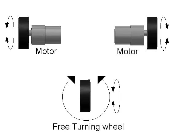
The robot we have designed is a differential wheeled/drive robot. In a differential wheeled robot, the movement is based on two separately driven wheels placed on either side of the robot's body. It can change its direction by changing the relative rate of rotation of its wheels, and hence, doesn't require additional steering motion. To balance the robot, a free turning wheel or caster wheels may be added. The following diagram shows a typical representation of a differential drive:
Differential wheeled robot
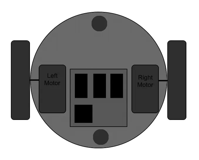
If the two motors are in the same direction, the robot will move forward or backward. If one motor has more speed than the other, then the robot turns to the slower motor side; so, to turn left, stop the left motor and move the right motor. The following diagram shows how we connect the two motors in our robot. The two motors are mounted on the opposite sides of the base plate and we put two casters in the front and back of the robot for balancing:
Top view of robot base
Next, we can program the motor controller using Launchpad according to the truth table data. Programming is done using an IDE called Energia (http://energia.nu/). We are programming Launchpad using the C++ language, very simila...