Learning Robotics using Python
Design, simulate, program, and prototype an autonomous mobile robot using ROS, OpenCV, PCL, and Python, 2nd Edition
- 280 pages
- English
- ePUB (mobile friendly)
- Available on iOS & Android
Learning Robotics using Python
Design, simulate, program, and prototype an autonomous mobile robot using ROS, OpenCV, PCL, and Python, 2nd Edition
About this book
Design, simulate, and program interactive robots
Key Features
- Design, simulate, build, and program an interactive autonomous mobile robot
- Leverage the power of ROS, Gazebo, and Python to enhance your robotic skills
- A hands-on guide to creating an autonomous mobile robot with the help of ROS and Python
Book Description
Robot Operating System (ROS) is one of the most popular robotics software frameworks in research and industry. It has various features for implement different capabilities in a robot without implementing them from scratch.
This book starts by showing you the fundamentals of ROS so you understand the basics of differential robots. Then, you'll learn about robot modeling and how to design and simulate it using ROS. Moving on, we'll design robot hardware and interfacing actuators. Then, you'll learn to configure and program depth sensors and LIDARs using ROS. Finally, you'll create a GUI for your robot using the Qt framework.
By the end of this tutorial, you'll have a clear idea of how to integrate and assemble everything into a robot and how to bundle the software package.
What you will learn
- Design a differential robot from scratch
- Model a differential robot using ROS and URDF
- Simulate a differential robot using ROS and Gazebo
- Design robot hardware electronics
- Interface robot actuators with embedded boards
- Explore the interfacing of different 3D depth cameras in ROS
- Implement autonomous navigation in ChefBot
- Create a GUI for robot control
Who this book is for
This book is for those who are conducting research in mobile robotics and autonomous navigation. As well as the robotics research domain, this book is also for the robot hobbyist community. You're expected to have a basic understanding of Linux commands and Python.
Tools to learn more effectively

Saving Books

Keyword Search

Annotating Text

Listen to it instead
Information
Interfacing Actuators and Sensors to the Robot Controller
- Interfacing a DC-geared motor with Tiva C LaunchPad
- Interfacing a quadrature encoder with Tiva C LaunchPad
- An explanation of interfacing code
- Interfacing Dynamixel actuators
- Interfacing ultrasonic sensors and IR proximity sensors
- Interfacing inertial measurement units (IMUs)
Technical requirements
Interfacing DC geared motor to Tiva C LaunchPad
- Two Pololu metal gear motors, 37Dx73L mm with 64 counts per revolution encoder
- Pololu wheel, 90x10 mm and a matching hub
- Pololu dual VNH2SP30 motor driver carrier, MD03A
- A sealed lead acid/lithium ion battery of 12V
- A logic level convertor of 3.3V to 5V; visit https://www.sparkfun.com/products/11978.
- A Tiva C LaunchPad and its compatible interfacing wires


| INA | INB | DIAGA/ENA | DIAGB/ENB | OUTA | OUTB | CS | Operating mode |
| 1 | 1 | 1 | 1 | H | H | High Imp | Brake to Vcc |
| 1 | 0 | 1 | 1 | H | L | Isense = Iout / K | Clockwise (CW) |
| 0 | 1 | 1 | 1 | L | H | Isense = Iout / K | Counterclockwise (CCW) |
| 0 | 0 | 1 | 1 | L | L | High Imp | Breaker to GND |
Differential wheeled robot
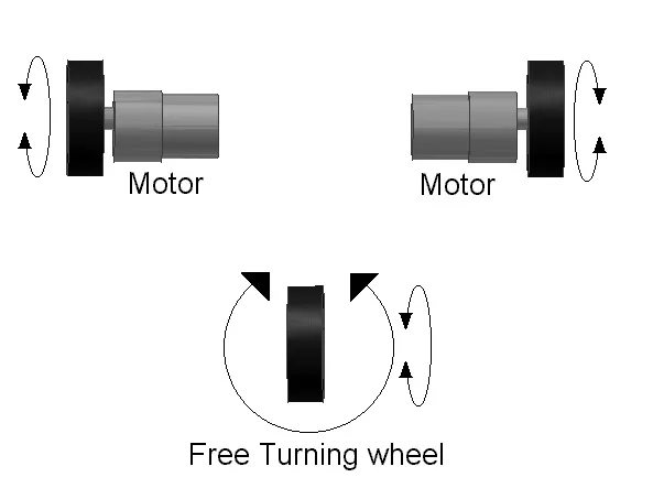
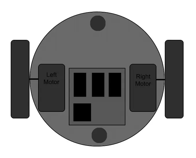
Table of contents
- Title Page
- Copyright and Credits
- Dedication
- Packt Upsell
- Contributors
- Preface
- Getting Started with Robot Operating System
- Understanding the Basics of Differential Robots
- Modeling the Differential Drive Robot
- Simulating a Differential Drive Robot Using ROS
- Designing ChefBot Hardware and Circuits
- Interfacing Actuators and Sensors to the Robot Controller
- Interfacing Vision Sensors with ROS
- Building ChefBot Hardware and the Integration of Software
- Designing a GUI for a Robot Using Qt and Python
- Assessments
- Other Books You May Enjoy
Frequently asked questions
- Essential is ideal for learners and professionals who enjoy exploring a wide range of subjects. Access the Essential Library with 800,000+ trusted titles and best-sellers across business, personal growth, and the humanities. Includes unlimited reading time and Standard Read Aloud voice.
- Complete: Perfect for advanced learners and researchers needing full, unrestricted access. Unlock 1.4M+ books across hundreds of subjects, including academic and specialized titles. The Complete Plan also includes advanced features like Premium Read Aloud and Research Assistant.
Please note we cannot support devices running on iOS 13 and Android 7 or earlier. Learn more about using the app