![]()
Chapter 1
Diffraction Analysis of Defects: State of the Art
Rozaliya I. Barabash and Gene E. Ice
Materials Science and Technology Division,
Oak Ridge National Laboratory,
Oak Ridge, TN 37831, USA
Materials’ properties are largely determined by the self-organization and collective behavior of defects. A number of X-ray methods including Laue microdiffraction, rocking curve measurements and reciprocal space mapping can be used to characterize mesoscale dislocation structures and elastic strain. This chapter describes how dislocations and other common defects cause local strain field fluctuations and alter the structure factors of the cells in which they occur, as well as in neighboring cells. These changes alter the diffraction conditions in reciprocal space, and result in characteristic features in the diffracted intensity. These diffraction features can be used to model the local strain and dislocation structure of advanced materials. Different dislocation arrangements are considered such as: randomly distributed statistically stored dislocations (SSDs) and geometrically necessary dislocations (GNDs); dislocation loops; dislocation dipoles; dislocation boundaries including incidental dislocation boundaries (IDBs) and geometrically necessary boundaries (GNBs). The impact of twins is also discussed.
1.1. Defect Classification in the Kinematic Approximation
Defects break the long-range symmetry of a crystal lattice and displace atoms from their ideal positions. To understand how defects impact on diffraction, it is necessary to address four questions:
1. How do defects distort the lattice?
2. Are the defects ordered and/or correlated?
3. Do they change the structure factors of their unit cells and surrounding unit cells?
4. Do they interact with external fields?
As is well known, the scattering from atoms of an ideal perfect crystal add constructively under the Bragg–Laue conditions, which results in δ-function-like intensity maxima localized at reciprocal lattice sites of the crystal. Real crystals always contain defects, which perturb the ideal periodic arrangement of the atoms and change local structure factors. The qualitative nature of diffracted intensity depends on whether it is possible to relate the atomic positions to an average lattice. If the defects cause atomic displacements, which are localized in the immediate vicinity of the defects, then it is possible to relate a single periodic lattice to the crystal; typically, if the mean square fluctuations of the atomic displacements remain finite and do not exceed the interatomic distance, then it is possible to relate an average periodic lattice to the crystal with defects. These defects are called “defects of the first kind” (Krivoglaz, 1969, 1996).
Some defects distort the lattice in a manner that makes it impossible to reference atomic positions to a single periodic lattice. However, it is often still possible to relate slightly different periodic lattices to relatively large parts of the crystal (for example, subgrains, dislocation cells, etc.). Such defects are called “defects of the second kind” (Krivoglaz, 1969, 1996).
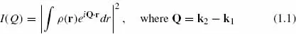
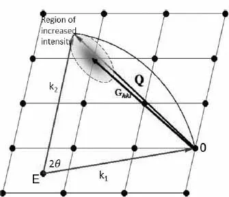
For the analysis of the diffraction, an Ewald sphere representation is usually used (Fig. 1.1). In this representation, k2 and k1 are the wave vectors along the diffracted and incident beam. In the kinematic approximation, complex scattering amplitudes from the electron probability density are integrated with the corresponding phases to determine the scattering intensity, I(Q), for diffraction vector or momentum transfer, Q. In electronic units, intensity of scattering by a monochromatic beam is described by the equation (Krivoglaz, 1969, 1996):
Here, ρ(r) is a total electron probability density at position vector r. Integration in Eq. 1.1 is performed over the whole scattering volume. For an infinite ideal crystal, the intensity distribution as a function of momentum transfer will consist of the δ-function-like peaks positioned at the reciprocal lattice sites.
Fig. 1.1. Ewald representation of the diffraction experiment: Ghkl is a reciprocal lattice vector, Q is a diffraction vector or momentum transfer and 2θ is a scattering angle between the incident k1 and scattered k2 radiation wave vectors with wavelength λ. The origin of the reference reciprocal lattice frame, 0, is located at the end of the incident k1 vector. The origin of the Ewald sphere with a radius |k1| = |k2| = 2π/λ is positioned at E. The ends of the momentum transfer, Q, and wave vectors k1 and k2, must be on the surface of the Ewald sphere. If Q = Ghkl, the Ewald sphere passes through one more reciprocal lattice site and Bragg–Laue diffraction will occur in the direction of the k2 vector. If the condition Q ≠ Ghki is not satisfied, as shown in the figure, the Bragg–Laue diffraction will not occur for this reflection, instead the diffuse scattering will originate from the region of increased intensity around the (hkl) reciprocal lattice point.
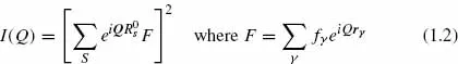
For crystalline materials, it is convenient to write Eq. 1.1 in terms of the scattering from unit cells that fill the real-space crystal lattice with repeated structures. The complex scattering amplitudes from each unit cell—called the structure factor, F — are summed to determine the total scattering from the crystal.
Here, the index
s labels the unit cell sites with positions
;
γ are the atoms in each unit cell with relative positions
rγ;
F is the structure factor; and
fn is the atomic scattering factor of the
nth atom of a unit cell.
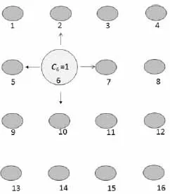
Fig. 1.2. Sketch of crystal lattice plane with one point defect in the position t = 6. Only c6 = 1, for all other lattice sites ct = 0.
Defects typically redistribute the scattering intensity expected from a perfect crystal. Defects displace surrounding atoms (unit cells) and change the scattering factor of the unit cells in which they are embedded. To describe the distribution of defects, we adopt the random numbers ct (Krivoglaz, 1969, 1996) such that:
In the example given in
Fig. 1.2, only
c6 = 1 and at all other lattice sites,
ct = 0. In the ideal crystal the lattice site positions without any defects are characterized by the position vector
, and positions of defects by the vector
. Each unit cell will be identified by its number,
s. If the unit cell consists of several atoms then the position of atoms inside the unit cell will be numbered by the index,
γ. The defect positioned on the lattice site,
t, creates a partial displacement,
ust, and partial rotatio...