![]()
Chapter IV
Polarized Light And Crystals
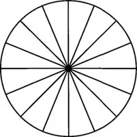
Up to this point we have considered light as a wave motion which vibrates in space in all directions. Looking at a beam of light the vibration directions are in all radial directions perpendicular to the direction of propagation.
Figure IV-1. Vibration directions in a beam of unpolarized light propagating perpendicular to this page.
When the vibration directions line up with each other the beam is said to be polarized. This situation gives the beam some unique properties which we will examine after seeing how to create polarization. First we must look at some other properties of light.
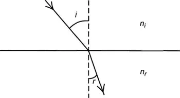
In 1621 Willobrord Snell the Dutch astronomer observed the difference in paths between an incident and refracted ray and determined that ni sin i = nr, sin r when ni and nr represent the indices of refraction of the two media and αi and αr are the angles of incidence and refraction that the ray makes with the normal to the boundary. The path of the light ray is bent toward the normal when the ray enters a substance with an index of refraction higher than the one from which it emerges. This is another way of saying as in Chapter I that the ray enters a higher density space from a lower density space. The converse is that when the path of the ray is from a higher index to a lower index the ray is bent away from the normal.
Figure IV-2. Light path between two media of differing refractive index.
The refractive index of a substance is the ratio of the speed of light in a vacuum to the speed of light in the substance. This index will vary with the wavelength (or color) of the light. The spreading of a mixture of wavelengths producing a spectrum is called dispersion. This of course is the reason for the color fringes produced in early microscopes before Hall conceived the concept of the achromatic lens. Later lenses corrected both for chromatic aberration and spherical aberration were called apochromatic.
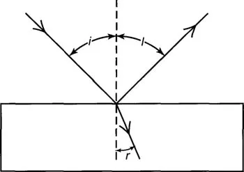
When light is reflected from a surface the angle of incidence (i) equals the angle of reflection (1) however at a certain angle (the polarizing angle) the reflected light becomes almost completely polarized. Sir David Brewster in 1799 began investigating this phenomenon and determined a simple relationship between the polarizing angle and the refractive index of the reflective substance.
Figure IV-3. Brewster’s angle; the angle of maximum polarization.
By 1812 Brewster observed that the incident ray gives rise to two partially polarized rays. The reflected ray whose vibrations are perpendicular to the plane of incidence and the refracted ray whose vibrations are mainly within the plane of incidence. He reported that these two rays obtained their maximum degree of polarization when the angle of incidence and the angle of refraction were complimentary, that is when: cosi = sinr. This is one way of producing polarized light by reflection. There are several other ways that we will now look at.
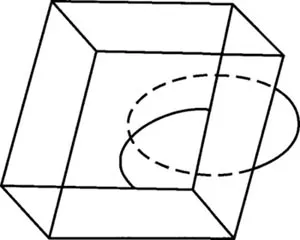
In 1669 a Danish scientist Erasmus Bartholin discovered that a ray of unpolarized light incident on a plate of the mineral calcite is split into two rays. One ray called the ordinary ray is in the plane containing the incident ray and the normal to the surface. When the angle of incidence is varied this ray obeys Snell’s law. The other ray called the extraordinary ray is usually not coplanar with the incident ray and the normal and for it the ratio of sines (Snell’s law) is not constant.
Figure IV-4. Calcite rhomb showing double refraction.
The fact that Snell’s law is not obeyed in certain directions implies that the velocity of light in such a medium depends on the direction of travel in it. The two rays are polarized in mutually perpendicular planes. This medium is called anisotropic and will be discussed later along with other properties of crystals. A medium that does not exhibit double refraction is called isotropic and is typically a glass or a very high symmetry crystal.
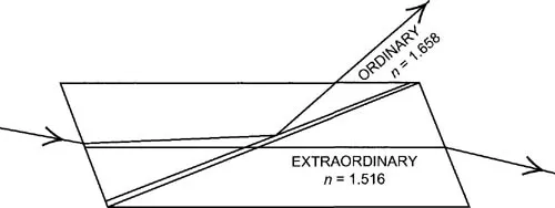
William Nicol made use of the polarizing properties of calcite to construct a prism that transmits a single beam of plane polarized light. This prism is made by cutting a calcite crystal in a suitable plane relative to the crystal axis and cementing the two parts together with Canada balsam. The critical angle for total reflection is less for the ordinary ray than for the extra ordinary ray. The crystal is cut at such an angle that for a cone of incident rays of about 24° the ordinary ray is totally reflected and the extraordinary ray is transmitted.
The extra ordinary ray has an index of refraction of 1.516 at the angle of incidence of the prism. The ordinary ray has an index of 1.658. The material used to cement the prism is Canada Balsam which has an index of 1.537. The index of the extraordinary ray is close to that of the balsam but the index of the ordinary ray is considerably greater. Both rays strike the cementing plane of balsam obliquely but the angle of the ordinary ray exceeds the critical angle and it is reflected out through the side of the prism. The ordinary ray which does not exceed the critical angle passes through the prism and therefore light emerging from the prism is polarized in only one plane. Crossed Nicols means, two nicol prisms are superimposed with their planes of polarization at right angles. A beam of unpolarized light entering one prism will not leave the second prism producing darkness at the exit of the second prism. If an isotropic material is placed between the prisms the situation does not change and there is still darkness. If an isotropic material is placed there then interference colors will be seen leaving the second prism. This effect will be discussed later after the discussion of crystals.
Figure IV-5. Nicol prism which transmits a single beam of plane polarized light.
The polarizing prisms in use in modern microscopes are referred to as “Nicols” although they may be made differently and may not even have any calcite inside.
A third means of polarizing light makes use of polarization by absorption. Many crystalline substances have different absorption coefficients for the ordinary and extraordinary rays but this is usually too small to be useful. In 1852 William Bird Herepath, a physician described crystals of a strongly absorptive compound iodo-cinchonidine-sulfate. In recent time methods have been developed for producing thin transparent sheets containing small crystals of this material in parallel orientation in a polymer binder. The orientation is achieved by stretching the polymer. This in effect acts like a single crystal of large area and is known commercially as “Polaroid”. This material will transmit about 80% of plane polarized light which is vibrating in one plane and less than 1% vibrating in a perpendicular plane. This “Polaroid” material offers a convenient way of obtaining a beam of plane polarized light and has many applications. Since we have seen that reflected light is polarized to a greater or lesser degree Polaroid finds use in sunglasses that are efficient in cutting glare by cutting out all the light vibrating in directions other than the plane of polarization of the filter.
Some years before Nicol invented his polarizing prism he had used Canada balsam to cement pieces of fossils and minerals onto a glass plate and then ground them down thin enough to see through them on a microscope. He observed such things as bubbles in minerals and the cells in plant fossils that showed the kind of plant that had been fossilized. In 1827 he observed, without a microscope, slices of materials between a pair of Nicols whose planes of polarizations were at right angles to one another. This positioning of the prisms is referred to as “crossed nicols” and demonstrated interesting optical effects such as anisotropy which we will see later in this chapter. It was Henry Fox Talbot, one of the fathers of photography who was the first to equip a microscope with a pair of polarizers in 1834. By 1949 Henry Clifton Sorby began to prepare thin sections of rocks (about 0.025 mm thick) for microscopic study and began to report the optical properties of minerals. During the next few years the demand for special polarizing microscopes was low. People who wanted to study thin sections of rocks and minerals had to make do with adding polarizing prisms to their own microscopes. In 1885 Ernst Leitz in Wetzlar, Germany introduced a special polarizing microscope which soon became an important tool for mineralogists, geologists and chemists.
In order to understand the images seen in a polarizing microscope we have to look at some of the properties of crystals. A crystal is a solid made up of atoms periodically arranged in space. This periodicity is what gives a crystal its properties in contrast to a glass whose atoms are randomly arranged. This randomness is also true of a liquid except for special cases to be discussed later. This brief definition has been arrived at over several hundred years of investigation and really does not fully describe all of the observed properties of crystals. The external form of many crystals is characterized by plane faces arranged in a symmetrical manner. Crystals with faces have been observed since the times of the ancient Greeks. In 1669 Nicolaus Steno, a Danish anatomist measured the angles between similar kinds of faces on a large number of quartz crystals from many different places. He made the remarkable discovery that the angles between similar faces on many different crystals of the same material were the same. This was one of the first concepts about crystals to be recorded and is now called the “law of constancy of interfacial angles”. It took almost a hundred years more for this to lead to the concept of a crystal’s properties being the result of the regularity of its internal structure.
A sense of symmetry is an important tool to develop a classification of crystals. This use of symmetry can be a key to organizing the endless array of atoms that make up the crystalline solids. Symmetry is the result of operations that bring an object or a pattern into coincidence with itself. There are only a few symmetry operations.
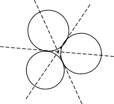
For instance if the object in Figure IV-6 is rotated 120° around an axis perpendicular to the page then it will occupy a position which is indistinguishable from its original position. This operation is a symmetry operation and since it occurs three times during a full rotation the axis is called a 3-fold symmetry axis. Consider an axis lying in the plane of the paper that passes between two of the circles and through the center of the third. Rotation around this axis for 180° will bring the circles into coincidence. This is a 2-fold symmetry axis.
Figure IV-6. Three fold symmetry.
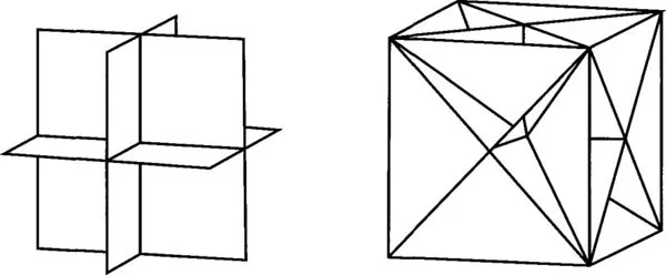
Looking at real crystals another axis that is observed is 4-fold. This really includes a 2-fold axis but the higher symmetry has preference. In addition to axes of 2-fold, four fold, three fold and six fold, further observation of real crystals demonstrates the existence of planes of symmetry. A plane of symmetry acts like a mirror. A demonstration of planes of symmetry in a simple crystal form, the cube, is shown in Figure IV-7.
Figure IV-7. Symmetry planes in a cube.
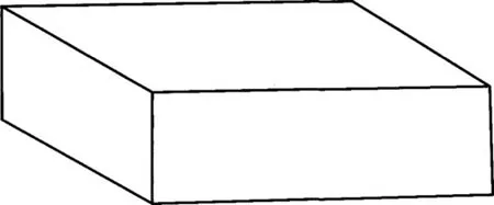
In addition to planes and axes there is a third kind of symmetry element. We can examine this by looking at an orthogonal block that has no square faces.
Figure IV-8. This block has a center of symmetry.
This block has symmetry planes and axes. Whatever feature of this block we look at, e.g. a corner or an edge, at an equal distance from the center of the block the same feature occurs. If we draw a line from the center to a corner continuing the line through the center; at the same distance from the center it will meet a copy of the original corner. This feature is the element called a center of symmetry, and the operation is called inversion through the center.
Symmetry operations were first observed in the relationships of faces in real crystals. Many thousands of crystals were measured and described. Based on the axes of symmetry their relative length and the angles between their crystals can be divided into a simple classification of 6 crystal systems.
1) The cubic system also called the isometric system has three crystal axes at right angles to each other and of equal length.
2) The tetragonal system has three crystal axes at right ...