![]()
Chapter 1
Introduction to Heating, Ventilation and Air Conditioning
1.1An Overview of HVAC Systems
The commonly used acronym for heating, ventilation and air conditioning is HVAC. In its broadest sense, HVAC encompasses the means, the processes, and the technology used to maintain an indoor space at a desired set of physical conditions. Typically these conditions depend on the type of activity for which the space is used. For instance, if the space is the inside of a building occupied by people, the most pertinent conditions are the temperature, the humidity level, and the cleanliness of the air.
The indoor conditions for a health facility like a hospital or a clinic would be similar, but they would have to be controlled within more stringent limits compared to those of an ordinary home. In the case of a process plant, such as a food preparation facility or a paint-shop, the indoor conditions would have to satisfy those mandated by the industrial guidelines for these processes.
The conditions of all indoor environments are dynamic because they are subject to various time varying inputs, some of which are predictable while others are random or accidental. In the case of a residential building or a home, the indoor temperature, humidity, and cleanliness of the indoor air change due to a number of inputs which can be internally or externally generated.
The temperature difference between the indoor air and the ambient air causes heat to flow across the building envelope. During winter, when the temperature outside is lower than the indoor temperature, heat is lost to the outside. This makes the inside air colder, and therefore uncomfortable for occupants. The HVAC system needs to balance this heat loss by supplying the necessary heat input, using an external energy source. In addition, cold air leaking through any openings and cracks in the building envelope has to be heated to the indoor temperature by the HVAC system. If the indoor air is too dry and therefore uncomfortable for the occupants, moisture has to be introduced artificially. The total amount of energy supplied by the HVAC system per unit time, to maintain the space at the desired temperature and humidity, is referred to as the winter heating load of the building.
In the summer, the air outdoors is usually hotter and more humid than the typical indoor comfort conditions stipulated. In this case the heat flow across the building envelope occurs in the opposite direction. Moreover, the indoor air is heated indirectly by the solar radiation entering through the glass surfaces of the building envelope, such as, windows, glass doors, and skylights. The transmitted solar radiation is first absorbed by the interior surfaces of the building like the walls, the floor, and other items, such as furniture. This absorbed energy is later released to the indoor air when the latter surfaces get warmer.
People occupying the building, the indoor lights, and appliances, such as, computers and coffee makers, also release heat and moisture, which increases the temperature and humidity of the indoor air. If comfortable indoor conditions are to be maintained steadily, then all the aforementioned heat and moisture flows have to be balanced by the HVAC system. The amount of energy that needs to be removed by HVAC system per unit time is called the cooling load of the building. It is interesting to note that in the winter, the energy inputs, like absorbed solar radiation, energy from people, lights and equipment, tend to heat the indoor air, and thereby reduce the heating load of the building.
In section 1.2 below we shall present a few optional designs of HVAC systems including some of the equipment used. But first, it is instructive to highlight the interactions between the conditioned space and the HVAC system by referring to the conceptual diagram depicted in Fig. 1.1.
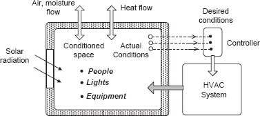
Fig. 1.1 Conceptual diagram of HVAC system
Within the indoor conditioned space shown in Fig. 1.1 energy is released by people depending on the type of activities they are engaged in. People also add moisture to the air and thereby increase the humidity of the air. The artificial lights inside the space and equipment, such as, computers, fax machines, coffee makers, and others produce heat that flows into the air. Solar radiation transmitted through the transparent sections of the enclosure, like the glass windows of a building, contributes indirectly to the heating of the air inside. Sensible heat is gained or lost through walls of the enclosure due to the inside-to-outside temperature difference. There may also be unwanted leakage of air and moisture through cracks and openings in the enclosure. As a consequence of these energy flows the conditions of the air inside the enclosure, such as, the temperature and humidity, change continuously.
The conditions of the space are monitored by sensors located inside, and the data is transmitted to a controller. This could be a simple thermostat in the case of a HVAC system serving a residence. In the case of a modern commercial building, the control system could be a computer based building management system (BMS).
The controller compares the actual conditions of the space with the desired conditions supplied to it by the designers of the HVAC system or its operators. Based on the discrepancy between the actual and desired conditions, the controller activates the necessary hardware items of the HVAC system to reestablish the desired conditions within the space. The HVAC system does this by either supplying or removing the appropriate amount of energy and moisture from the space. Careful control of the inside conditions, at the desired values, contributes both to the comfort of the occupants of the space and to the overall energy efficiency of the system.
1.2Some Optional Designs of HVAC Systems
We shall now consider a few optional designs of HVAC systems that are being used for building related applications. However, these same designs could be modified for industrial and transportation applications where the requirements may be somewhat different.
1.2.1HVAC system using air as the energy transport medium
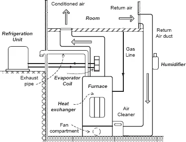
Shown schematically in Fig. 1.2 is an HVAC system, commonly used for heating and cooling residences and small commercial buildings.
Fig. 1.2 Typical forced air heating and cooling system for homes
Air from the rooms or the conditioned spaces of the building is drawn by a fan, through a filter, to be processed by the HVAC system. In the heating mode of operation, the air passes over the tubes of a heat exchanger through which hot combustion gases flow in the opposite or ‘cross-flow’ direction. The combustion process occurs in a chamber that is usually supplied with a fuel, such as, natural gas. The heated air then flows through the supply duct network to the various spaces of the building. If necessary, the moisture content of the air can be increased by activating the humidifier located in the return air duct.
Typically, the temperature of the building is controlled by a thermostat located in one of the rooms. If the temperature of the room exceeds the preset temperature the thermostat switches off the combustion process, thus shutting down the furnace. The operation is reversed when the space temperature falls below the preset value.
In the cooling mode of operation, the furnace is shut down, and the compressor of the refrigerator is switched on. In most HVAC systems, the evaporator coil of the refrigerator is located in the supply air duct, as shown in Fig. 1.2. The condensing unit of the refrigerator, including the compressor, is usually placed outdoors. The air flowing over the finned tubes of the evaporator coil is cooled and dehumidified, and the condensate from the air is drained by gravity, to a sump in the plant room. When the temperature of the space falls below the preset temperature, the thermostat switches off the compressor. In this type of simple system the thermostat has to be manually set to either the heating or cooling mode of operation, depending on the outdoor conditions.
1.2.2HVAC system using water as the energy transport medium
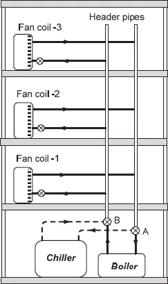
An HVAC system using water as the energy transfer medium is shown schematically in Fig. 1.3.
This system is equipped with a boiler, for producing hot water to be used in the heating mode of operation, and a water chiller, to be used in the cooling mode of operation. The water chiller is essentially a refrigerator, where the evaporator coil is used to produce chilled water, typically at a temperature of about 3 to 5°C. The system depicted in Fig. 1.3 is called a two-pipe arrangement [2]. As in the case of the HVAC system described in section 1.2.1, the all-water, two-pipe system either operates in the heating mode or the cooling mode at any one time.
In the heating mode of operation, the two header pipes that circulate water are connected to the boiler through valves A and B. The hot water from the supply header pipe flows through heat exchanger tubes in the fan coil units. Air from the room is circulated over the finned tubes by means of a fan located inside the fan coil unit. The flow rate of water through the fan coil is usually controlled by valves at the inlet, which could either be operated manually, or by means of a thermostat, to maintain the desired room temperature.
Fig. 1.3 All-water, two-pipe heating and cooling system
In the cooling mode of operation, the same header pipes are connected to the water chiller by repositioning the valves A and B. The chilled water flowing through the fan coils, from the supply header pipe, cools and dehumidifies the room air circulated through them by the fans. Any condensate produced within the fan coil units is piped out to a sink.
The two-pipe system shown in Fig. 1.3 cannot handle simultaneous heating and cooling needs of different rooms. If some rooms served by the system have high heat loads, and therefore require cooling, while others require heating, then the two-pipe system is not a suitable design option. However, two-pipe systems are less complicated and require fewer pipes, fan coils, valves, and controls.
A more versatile all-water system is the four-pipe system [2,4]. It has fan coil units which incorporate separate heating and cooling coils. These are connected to separate hot water and chilled water header pipes, similar to those in shown Fig. 1.3. The two sets of header pipes, in turn, are connected separately to the boiler and the chiller. When the boiler and the chiller are both operating, a fan coil unit can be rapidly switched between heating and cooling modes, by means of the valves at the inlets of the heating and cooling coils. Therefore these systems can provide heating to some rooms, while simultaneously providing cooling to other rooms of the building. The disadvantage, however, is that they requires more pipes, heat exchangers, and controls.
1.2.3HVAC system using water and air as energy transport media
A central HVAC system using both air and water as energy transport media is shown schematically in Fig. 1.4. Return air from the conditioned space is drawn into the air handling unit (AHU) by the return air fan. As the air passes through the AHU a fraction of it is discharged to the outside ambient through the exhaust port EA, and replaced with an equal amount of fresh ambient air drawn through the inlet port OA, for hygienic reasons. Dampers are used to control this process. The mixture of return air and fresh air then passes through a filter before entering the cooling and dehumidifying coil.
In the cooling mode of operation, the air passing over the cooling coil is cooled and dehumidified, and the condensate produced is drained out from the AHU. The supply air fan then distributes the cold air through the supply duct network to the conditioned space.
Finally, the desired quantity of air is discharged to each conditioned space or room through flexible ducts connected to ceiling diffusers in the space.
In the heating mode of operation, the cooling coil is inactive, while the air is heated by water flowing through the hot water coil, and hot air is distributed to...