![]()
Chapter 1
Electronics Engineering
Research on the characteristics of inductance of interior permanent magnet synchronous motor
X. Wu†, S.H. Wang and Z.M. Gao
College of Electrical and Power Engineering, Taiyuan University of Technology,Taiyuan, 030024 China†Email: [email protected] Y.T. Wang
State Grid of Shandong, Binzhou, 256600 China
Corresponding related expressions of current between d-q axis and stator three phase were derived, then to analyze the impact of characteristic of inductance when there were armature excitation, permanent magnet and incorporating of them. On this basis, influence to inductance considering iron saturation and cross effect was investigated. This paper takes an Interior Permanent Magnet Synchronous Motor (IPMSM) with 11kW, 380V as example, firstly Ansoft/Maxwell was used to establish the finite element simulation model, then Fixed Permeability Method (FPM) was applied to analyze laws between d-q axis inductance and current which include quadrate axis current, direct axis current and both of them, by the way, laws of d-q axis inductance and rotor position was obtained. This paper is significant for analyzing and designing of PMSM.
Keywords: D-q axis inductance; Fixed permeability method; Finite element; Iron saturation.
1.Introduction
Permanent magnet synchronous motor has advantages such as small power density, high efficiency and widely speed range [1-2], which makes it widely used in daily life. One of the most significant aspects is that inductance parameters of the motor were calculated accurately before prototype production.
Magnetic conductivity analysis [3-4] and magnetic fields analysis methods are mainly used to calculate inductance parameters. For magnetic conductivity analysis, multi-loop analysis way [5] was employed mostly because of the completed theory. Literature [6] derived the unified expressions for calculating inductance by simplifying the multi-loop method and only considering fundamental air-gap MMF, but this expression is only fit for the situation when the rotor is at a particular position or the stator current is a certain number. Magnetic fields analysis method is a new method with the development of finite element software. Literature [7] obtained rules of stator self inductance and mutual inductance with rotor position by adopting AC standstill method, but the influence of saturation and cross effect were not considered in the passage. KANG G H analyzed the effect of saturation in finite element software using mathematical way in [8], later on, NAJAFI S did the simulation with the model [9]. Literature [8] certificated correctness of FPM by comparing the result of multi-loop method and FPM, and operating the no-load and full-load experiments. Literature [10-11] got the steady parameters of inductance considering saturation and cross effect. d-q axis inductance was solved through Park transformation in literature [7-11], which can’t reflect the influence of d axis and q axis current on inductance intuitively.
In this paper, the coordinate transformation formula was fatherly deduced to obtain corresponding related expressions of current between d-q axis and stator three phase. d and q axis current and rotor position were parameterized to obtain laws between the characteristic of inductance and them, which considering saturation and cross effect by using FPM.
2.Current and Inductance of D Axis and Q Axis
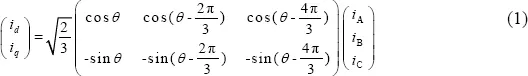
Formula of transformation from static ABC axis to d-q axis rotating at synchronous speed is as following [12]:
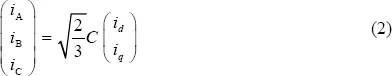
Where θ is expressed in electric angle between d axis and Phase A axis. The inverse matrix expression of formula (1) is:
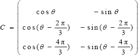
Where
The following relation between d-q axis current and stator current is existed:
Where
is is stator current;
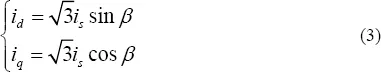
β is the angle between
iq and
is. Assuming that
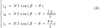
then formula(2) and (3) can be rewritten as formula(4).
Where N is turns of each floor of per slot; I is an intermediate variable.
Formula (4) shows that stator current and d-q axis current can be adjusted by changing β when θ=0. Such as following:
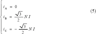
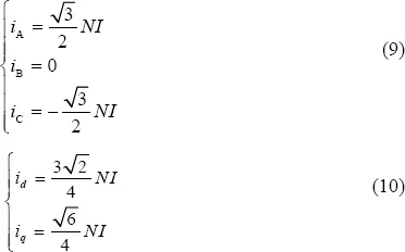
i. When β=0, stator current can be calculated according to formula (4):
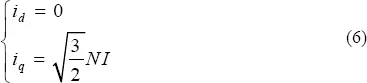
Thus d axis current and q axis current can be calculated:
Formula (6) shows that only a certain q axis current value is existed when stator current is just as formula (5).
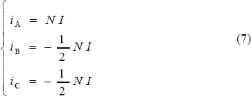
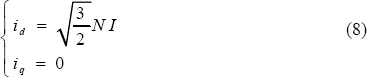
ii. When β=π/2, stator current and d-q axis current can be calculated:
At this time, it is equal to that only a certain d axis current value is existed.
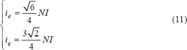
iii. β=π/3
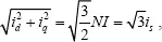
iv. β=π/6
At the situation iii & iv, it is equal to that both
d axis and
q axis current were existed. In the formula (6) (8) (10) (11), the following equation is existed that
from which the previous statement can be certified rightly.
Above all, by changing θ and β can not only realize q axis current and d axis current alone and together, but also can be intuitive shows the percentage of them. Three phase inductance matrix can be obtained immediately in Ansoft, in order to get the d-q axis inductance parameters, formula (12) is used.
Where CT is the transposed matrix of C; Lef is the effective length of iron core; M is the symmetric number of the finite element model.
3.Fixed Permeability Method
Fixed permeability method (FPM) is a new type of solving flux linkage with the development of finite software. It can disintegrate all of the flux linkage in motor to linkage caused by permanent magnet and stator current [13], thus inductance parameters will be obtained. There is no saturated for linear material since that the permeability is constant. For nonlinear ferromagnetic materials, the value of inductance will be different at different current because of different permeability. FPM changes a nonlinear problem into a linear problem by saving the value of permeability of per element after each calculation. The precision of meshing is very high when implementing FPM, procedures of FPM is as following:
Step 1: Calculating the rated conditions with nonlinear equations;
Step 2: Calculating the permeability of each element in step1;
Step 3: Frozen permeability of all elements in step2, then the value of permeability is constant;
Step 4: Calculating the condition without excitation and changing material to what in step3;
Step 5: Calculating the condition after applying excitation to the motor with linear equations;
Step 6: Calculating the value of inductance on the basis of energy method.
FPM was applied to calculate inductance parameters in the following content of this passage.
4.Rules of Inductance with D-Q Axis Current
4.1 Finite element model and excitation
This passage takes an IPMSM with 4 poles, 11kW, lap coil, Y connection, N=56, a=1, Lef=140mm, M=1, based on which the finite element model was established as
Fig. 2. In the subsequent analysis, in order to get inductance curves along with current, “
I” was parameterized to make
changed from -80A to 80A and
θ=0.
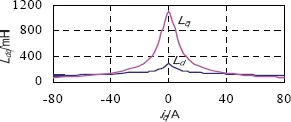
4.2 Inductance curves with q axis current
Current value shown in formula (5) was applied to stator to obtain curves along with q axis current. Fig. 1 shows waveforms of Lq and Ld.
Fig. 1 Curves of Lq and Ld along with iq.
Fig. 1 shows that curves of Lq and Ld are symmetrical about iq=0. With the increase of iq, ...