A hydraulic system controls the transmission of energy. It transforms the mechanical energy of a prime motor into fluid energy. It controls the fluid configuration and transforms the fluid energy into mechanical work at specified locations. Hydraulic s
- 328 pages
- English
- ePUB (mobile friendly)
- Available on iOS & Android
eBook - ePub
About this book
Trusted by 375,005 students
Access to over 1.5 million titles for a fair monthly price.
Study more efficiently using our study tools.
Information
Chapter 1
Introduction
In this chapter a simple hydraulic system is explained in detail, in order to clarify the principles of power control transmission making use of a liquid. Practical applications of hydraulic control systems are then illustrated using examples drawn from the field of aviation.
1.1 Basic Concepts and Formation of Hydraulic Systems
A hydraulic system is an energy transmission control system based on the use of a liquid. It transforms the mechanical energy of a prime mover into fluid energy, controls the energy in a fluid configuration and reconverts it into mechanical work at the chosen location. Since the fluid energy is both transmitted and controlled, power may be controlled by means of hydraulic valves driven by low electric power and low hydraulic power. When linked to a computer, the energy control transmission system offers several desirable features such as high power output, continuous and precise control, high-speed response, etc. Therefore, hydraulic control systems are widely applied in the transmission control systems in aircraft, ship, construction machinery, machine tools, etc. The equipment comprising hydraulic systems can be classified as follows.
(1) Energy-transforming components
There are various types of components that transform the mechanical energy of a prime mover into hydraulic energy. These are called hydraulic pumps or, more correctly, positive displacement pumps. An element that transforms hydraulic energy into mechanical work is called a hydraulic actuator, consisting of a hydraulic cylinder and a hydraulic motor. The hydraulic cylinder is an actuator performing a straight motion, whilst the motor is an actuator performing rotary work.
(2) Components controlling hydraulic energy
There are three kinds of control valves. These are pressure control valves to control pressure, directional control valves to control flow direction and flow control valves to control the flow rate in the hydraulic circuits. These are classified as components controlling the hydraulic energy. An accumulator accumulating fluid energy or absorbing the surge pressure may be classified as an energy-control element.
(3) Energy transmission components
Transmission lines, fittings, oil reservoirs, filters, heat exchangers and accumulators are classified as energy transmission components. They are also referred to as hydraulic system components.
A hydraulic pump is a positive displacement pump, which pushes out the fluid trapped in a pump chamber. Figure 1.1 illustrates the operating principle of a positive displacement pump. Each cylinder port has a check valve, one of which connects to the line with a reservoir while the other connects to the line with an actuator.
A check valve is a directional control valve which makes the fluid flow in a constant direction. As shown in Fig. 1.2, the flow in the direction indicated by the arrow passes through the check valve because a ball with a spring in the check valve is pushed aside by the differential pressure of the flow. However, flow in the opposite direction does not occur because the differential pressure on the ball pushes it back to close the flow passage.
In Fig. 1.1, the hydraulic fluid flows into the pump chamber through a check valve connecting a line with a reservoir, provided that the piston is moved in the left direction by the prime mover. Similarly, the hydraulic fluid in the pump chamber flows out through a check valve, provided that the piston is moved to the right by the prime mover. Moving the piston with a reaction force f at velocity v, the power w is transmitted to the piston by the prime mover, as shown in the following equation:
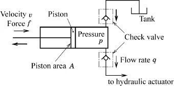
Fig. 1.1 Pump model.
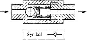
Fig. 1.2 Check valve.

Defining the displacement volume of the fluid per unit time as the flow rate, the flow rate q pushed out by the piston with the surface area A is described as follows:

Considering a pressure p that is generated in pump chamber depending on a load, the reaction force of piston f is denoted as follows:

The equation of power w is derived from Eq. (1.1) to Eq. (1.3)

Equation (1.1) yields the mechanical power fv, and Eq. (1.4) yields the hydraulic power pq which is transformed by the piston of the pump. Then the power is transmitted through the transmission lines in the form of a fluid configuration with pressure p and the flow rate q.
The output power of the system per unit system mass is called power density. High power density is one of the features of hydraulic control systems. Recalling Eq. (1.2) to Eq. (1.4), the power density rises by raising the system pressure, because the system components with small bulk can be adapted to the required power ratings by using high pressure and small flow rates. This is why high pressurization in hydraulic systems has been widely promoted.

Fig. 1.3 Swash plate type axial piston pump.
Figure 1.3 illustrates a swash plate type axial piston pump that consists of a cylinder block connecting with a driving shaft, a swash plate with piston shoes (slippers) and a valve plate (port plate). The cylinder block has several cylindrical bores located at a constant radius, and a piston is put into the bore. Though the piston shoes slide along a swash plate that is fixed at a constant inclination, they are able to move along a circular path on the swash plate surface. Considering the rotation of a cylinder block with pistons inserted in bores, each piston reciprocates along with the rotation because slippers connecting to the end of piston move along a circle on the swash plate surface. Then, the other end of cylindrical bore faces the suction side of the valve plate in the region increasing the volume of pump chamber, and it faces the delivery side of the valve plate in the region where the volume of pump chamber decreases. Therefore, a swash plate type axial piston pump is able to discharge hydraulic fluid continuously, without any check valves.
The piston stroke may be controlled by varying the plate’s inclination. Thus, a variable displacement pump can control the pump displacement by changing the inclination of the swash plate when the system is in operation. In contrast, a fixed displacement pump has the swash plate with a fixed inclined angle. Thus, it discharges the fluid at a fixed flow rate provided that the rotational velocity of a driving shaft is a constant.
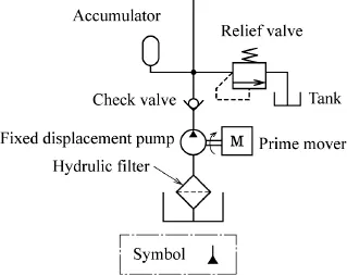
Fig. 1.4 Hydraulic source device.
Figure 1.4 shows a hydraulic source device called a tank unit using the standard graphic symbols for fluid power diagrams. Driving the prime mover, hydraulic fluid is suctioned into the pump chamber in a fixed displacement pump through a suction line from a reservoir, and then the pump discharges hydraulic fluid with fluidic power. The hydraulic fluid passes through a check valve and flows into a transmission line with an accumulator and a relief valve. The accumulator discharges fluid with fluidic energy when the pump displacement becomes temporarily insufficient. It has another role which absorbs the pressure fluctuation and surge pressure in the transmission line. The relief valve limits the maximum pressure in the transmission line.
Assuming that the fluid flow in a transmission line comes to a halt by closing the ports of the directional control valve, then, theoretically the pressure p could rise to infinity because fluidic power pq transmitted by the prime mover remains finite and the flow rate q becomes nearly zero. The relief valve and accumulator are provided in the transmission line, located near the pump, to avoid such sudden and excessive pressure changes. The relief valve maintains the pressure in the transmission line below the maximum permissible level by sending part of the pump flow rate through a tank port.
Figure 1.5 shows a functional structure of a balance piston type relief valve with a pilot valve having significantly small pressurized area compared to the main poppet valve.
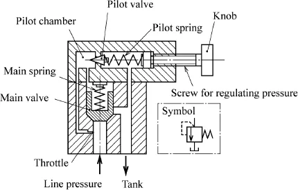
Fig. 1.5 Relief valve.
When the line pressure is lower than a cracking pressure corresponding to the pilot spring force, this force closes the pilot valve port. Then, the main spring force also closes the main valve port because the differential pressure between the upper and the lower does not occur. When the line pressure becomes higher than the cracking pressure, the pilot valve port begins to open. Then the differential pressure between the upper and the lower surface of the main valve is generated by the flow passing through a throttle in the pilot valve line, so that the main valve opens slightly and some of the fluid in the transmission line flows into the tank line through the main valves. Provided the deflection of the pilot spring is adjusted by operation of the knob with a spring so that all of the pump displacement passes through the main valve port at the allowable pressure in the transmission line, whose pressure keeps below the allowable maximum level.
As shown in Fig. 1.5, the standard graphic symbol of a relief valve consists of symbolic elements i.e. a broken line, an arrow and a block with a spring symbol and a reservoir symbol. The arrows in a block stand for the flow in a relief valve whilst a broken line denotes a pilot line pressure that controls the opening of the main valve port.
Figure 1.6 is an illustration of a diaphragm type accumulator. An elastic diaphragm separates the vessel of the accumulator into two parts. The upper chamber of the diaphragm is previously filled up with nitrogen gas that has about two-thirds of the system pressure, whereas the lower chamber of the diaphragm is connected to a transmission line of the hydraulic system.
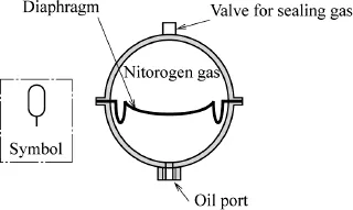
Fig. 1.6 Accumulator (diaphragm type).
As the hydraulic fluid in the transmission line flows into the lower chamber, the change of the gas volume in the upper chamber absorbs pressure ripples and surge pressure in the transmission line. It also performs the supplementary task of supplying the hydraulic fluid when the pump flow rate becomes temporarily insufficient. Thus, the hydraulic source device supplies the hydraulic ...
Table of contents
- Cover Page
- Title
- Copyright
- Contents
- Preface
- 1 Introduction
- 2 Fluid Mechanics for Hydraulic Control Systems
- 3 Hydraulic Components
- 4 Hydraulic Control Systems
- References
- Appendix
- Answers to Problems
- Index
Frequently asked questions
Yes, you can cancel anytime from the Subscription tab in your account settings on the Perlego website. Your subscription will stay active until the end of your current billing period. Learn how to cancel your subscription
No, books cannot be downloaded as external files, such as PDFs, for use outside of Perlego. However, you can download books within the Perlego app for offline reading on mobile or tablet. Learn how to download books offline
Perlego offers two plans: Essential and Complete
- Essential is ideal for learners and professionals who enjoy exploring a wide range of subjects. Access the Essential Library with 800,000+ trusted titles and best-sellers across business, personal growth, and the humanities. Includes unlimited reading time and Standard Read Aloud voice.
- Complete: Perfect for advanced learners and researchers needing full, unrestricted access. Unlock 1.5M+ books across hundreds of subjects, including academic and specialized titles. The Complete Plan also includes advanced features like Premium Read Aloud and Research Assistant.
We are an online textbook subscription service, where you can get access to an entire online library for less than the price of a single book per month. With over 1.5 million books across 990+ topics, we’ve got you covered! Learn about our mission
Look out for the read-aloud symbol on your next book to see if you can listen to it. The read-aloud tool reads text aloud for you, highlighting the text as it is being read. You can pause it, speed it up and slow it down. Learn more about Read Aloud
Yes! You can use the Perlego app on both iOS and Android devices to read anytime, anywhere — even offline. Perfect for commutes or when you’re on the go.
Please note we cannot support devices running on iOS 13 and Android 7 or earlier. Learn more about using the app
Please note we cannot support devices running on iOS 13 and Android 7 or earlier. Learn more about using the app
Yes, you can access Hydraulic Control Systems by Shizurou Konami, Takao Nishiumi in PDF and/or ePUB format, as well as other popular books in Technology & Engineering & Global Warming & Climate Change. We have over 1.5 million books available in our catalogue for you to explore.