![]()
Chapter 1
Principles of Radar Imaging of Ocean Processes
1.1.Radar Principles
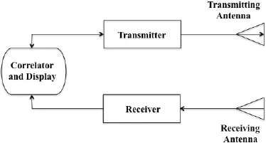
The term radar is an acronym for an electronic system that is used for Radio Detection and Ranging of remote targets [Skolnik, 1970]. As shown in Figure 1.1, a radar system comprises two elementary subsystems: a transmitter and a receiver with a correlator and display. The transmitter serves as a generator of radar waves. The receiver serves as a collector of echo signals returned from targets. The antennas perform transducers. Transmitting antenna converts the electrical currents fed by the generator into the electromagnetic (EM) fields and emits the EM waves to the free space with required radiation beam patterns. Vice versa, receiving antenna captures echo signals in the form of the EM fields from the space and converts the EM fields into the electrical currents and feeds the signals to the receiver. The receiver also has functions for data storage, processing and display.
In terms of remote sensing technology, the radar is a kind of active remote sensors. It illuminates targets with the EM energy transmitted by itself rather than by sunlight or infrared (IR) radiation of targets. Thus, the radar system has the ability to work day and night. The band of EM waves used by radars has strong penetration ability through cloud, fog, aerosol, smoke, rainfall and snowfall in the atmosphere. In other words, the radar system is able to work at all weather conditions. In addition, the radar waves also have good penetration ability through vegetation cover, dry soil, dessert, snow and ice cover and possibility being resonant with the target surface roughness. Thus, radars, including space-based radar, air-borne radar and ground-based radar, have become advanced remote sensors for detecting of the earth resources and environment. In particular, space-based radars are the most powerful tools for the ocean detection, owing to their sensitivities to the ocean dynamical processes to be discussed later.
Fig. 1.1 Elements of a radar system
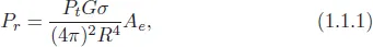
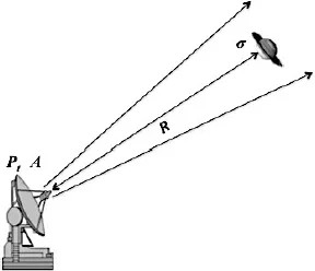
The radar system shown in Figure 1.1 has two separated antennas. In fact, for many types of operational radars, the transmitter and the receiver share the same antenna as shown in Figure 1.2. In this case, the relationship between EM power density Pr received by the antenna and transmitted EM power density Pt is formulated by
where G is the antenna gain, σ is the radar cross section (RCS), or scattering coefficient, of the target, Ae is the effective aperture (area) of the antenna, and R is the slant range from the antenna to the target. This is the so-called radar equation, which constitutes a theoretical fundamental for radar science and technology [Skolnik, 1970].
From Eq. (1.1.1), one can see that the intensity of radar echo that is represented by the received EM power density depends linearly on the RCS of the target. This implies that the radar echo contains the information on electrical properties and surface status of the target. Thus, RCS is the most important parameter for radar detection and target recognition functions. Physically, the RCS is a measure of ability of a radar target to reflect or scatter the radar waves in the direction of the radar antenna. For ocean radar remote sensing, the average RCS of per unit area of the ocean surface is a suitable parameter, which is a dimensionless, related quantity called the normalized RCS and defined as
Fig. 1.2 Schema for principles of a sharing antenna radar
where RCS is the radar cross-section of small waves on the ocean surface, and A0 is an area of the ocean surface illuminated by the radar waves, so-called radar antenna footprint. σ0 (sigma naught) usually is a very small quantity, but may vary within a quite large range. In application fields, therefore, its logarithmic form is commonly used, i.e.,
In addition, other two parameters in Eq. (1.1.1), effective aperture Ae and gain G of the antenna, determine the efficiency of EM energy transfer of the antenna. In fact, antenna gain G is closely linked to Ae through the relationship of
where λr is the wavelength of the EM waves, and
where Ka is the antenna aperture efficiency, and A is the aperture physical size. This implies that in the process of EM wave power transferred to the space, the effective aperture of radar antenna plays a critical role, which is a determinative parameter used for a measure of the performance of the antenna [The Ohio State University, 2014].
Equation (1.1.4) shows that for a given Ae, antenna gain G decreases quickly with the square of the wavelength of EM waves. This implies that there is an upper limit for the wavelength of EM waves that can be efficiently radiated to the space by the radar antenna. Besides the antenna gain, other factors, such as requirements for antenna radiation pattern, target characteristics and attenuation of the EM field in the air, must be also considered when choosing a radar wavelength band. The wavelength range used by state-of-art radars is from 1 to 100 m, i.e., the frequency ranges from 3 MHz to 300 GHz.
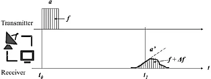
With this band of EM waves, the radar has two transmitting modes to be chosen: continuous wave transmitting mode and pulse wave transmitting mode, depending on mission requirements. Figure 1.3 shows a set-up process of a radar return signal in the case of pulse wave transmitting mode. The antenna transmitted a square pulse with amplitude a and frequency f of carrier waves at time t0, and received a return pulse from the target at times t1.
First, based on the time delay of the return pulse, the distance between the radar and the target can be calculated by
where C (= 2.998 × 10⁸ ms−1) is the speed of light. Then, one can see that the return pulse no longer has the same shape as the transmitted square pulse, but modified. From this return pulse, we can retrieve the following data and information:
Fig. 1.3 Set-up process of a radar return signal in the case of pulse wave transmitting mode.
RCS of target: Amplitude function a′(t) of return pulse can be used for calculation of the EM power density Pr received by radar antenna. Substituting the value of Pr into radar Eq. (1.1.1), RCS σ of the target can then be derived.
Target surface roughness: The widened frontal edge of return pulse contains the information of target surface roughness. In the case of the ocean, the frontal edge function is used to extract the significant wave height (SWH) of the s...