![]()
Chapter 1
Introduction to Reservoir Engineering
The main aim of this work is to understand how oil, water and gas flow deep underground with application to hydrocarbon recovery.
1.1.The Three Main Concepts: Material Balance, Darcy’s Law and Data Integration
Before I present any details, there are three main points that need to be understood by any good reservoir engineer. In the end, everything can be expressed with reference to one of these three fundamental concepts.
1.Material balance. Mass is conserved; what leaves a reservoir (is produced) minus what is injected is the change of mass in the sub-surface. For every field, under every circumstance, a reservoir engineer needs to check material balance — ideally by hand — to understand and interpret production data. This will be the basic principle on which I will base the analysis of fields under primary production. Furthermore, it lies at the heart of the derivation of the flow equations used to predict flow performance. However, for this we also need an equation for flow — point 2 below.
2.Darcy’s law for fluid flow. Fluid flows in response to a pressure gradient. The linear relationship between the gradient of pressure (or, more generally, the potential) and flow rate is Darcy’s law. It is the basis for any understanding and prediction of flow.
3.Look at all the data and have a coherent, consistent understanding of the field. A reservoir engineer assesses different information from several sources: geological interpretations, seismic surveys, log analysis, core analysis and fluid properties combined with production (rate and pressure) data. All of this data needs to be incorporated into a model of the reservoir to predict future performance and design production. A model in this context is not solely a complicated computer realisation of what the field might be like, but more a conceptual understanding of the field that includes the type of fluids present, the geological structure and the production mechanism. Too frequently, the time-consuming yet intellectually mundane task of operating reservoir simulation software overwhelms the effort to understand the field rationally; what are the major uncertainties in the understanding of the field, what data is needed to remove or reduce these uncertainties, what is happening now, what controls production and, physically, what are the consequences of alternative production strategies? The essence of good reservoir engineering is combining data, identifying uncertainty and describing production mechanisms. It is not playing computer games with sophisticated software as a smokescreen for a poor understanding of the basic mechanisms by which oil is produced.
1.2.What is a Reservoir and What is a Porous Medium?
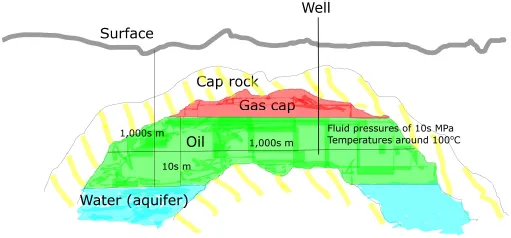
Figure 1.1 is a schematic of an oil field, which also contains gas, contained underneath impermeable cap rock. The diagram is reasonable, but rather underestimates the typical depth of the field. Usually, the oil is several kilometres below ground, while the depth of the column of oil itself is often less than 100 m. The areal extent is generally several square kilometres; later we will discuss some of the world’s larger oil fields, but the total volume of oil-bearing rock is typically around 109 m3, with, of course, a huge variation.
The gas and oil are held in the pore spaces of the rock at high temperatures and pressures. It is possible to estimate these values from the known depth and the geothermal gradient, as well as the pressure gradient. A typical geothermal gradient is 30°C/km, giving temperatures of around 100°C for reservoirs a few kilometres deep.
Figure 1.1. A schematic of an oil reservoir. The picture is reasonable, but the oil is generally found several kilometres below ground, while the water, oil and gas are all contained in porous rock.
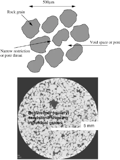
The oil and gas are held in a porous rock. What does this mean? Soils, sand, gravel, sedimentary rock and fractured rock all have some void space — i.e. gaps between the solid, as shown in Fig. 1.2. These systems are all porous media. If this space is continuous, in however a tortuous a fashion, it is possible for a fluid that occupies the voids to flow through the system — the material is said to be permeable. Soil, sand and gravel consist of small solid particles packed together. Consolidated rock is normally found deep underground where the individual particles have fused together. Volcanic rock that does not naturally contain any void space can still be permeable if it has a continuous pathway of fractures.
1.3.Fluid Pressures
The fluid pressure can be estimated from the weight of fluid above it in the pore space. Pressure increases with depth as
where Po is a reference pressure, ρ is the fluid density and g is the acceleration due to gravity = 9.81 ms−2.
Figure 1.2. Top, a schematic two-dimensional (2D) cross-section through a porous rock; bottom, a 2D cross-section of a 3D image of a sandstone showing individual grains. Approximately one quarter of the rock volume is void space. A porous medium contains void space — in reservoir engineering this void space may contain oil, gas and water.
Putting in representative values of depth and (water) density yields pressures of several tens of megapascals (MPa),1 or hundreds of times atmospheric pressure (which is approximately 0.1 MPa). We will use this equation later when it is employed to determine the depths of oil–water and gas–oil contacts.
In modern petroleum engineering, oil fields are detected through seismic imaging, where sound waves are sent through the rock; the returning waves detect changes in the acoustic properties of the rock and can be used to detect possible traps where hydrocarbons could accumulate. It is also possible in some cases to infer directly the likely presence of hydrocarbons.
Then an exploration well is drilled. You can never be sure that you have an oil field until you have drilled a well and oil is produced; the seismic image may have been wrongly interpreted, or the field might contain oil, but the flow rate is so slow as to make production uneconomic. When the well is drilled, fluid and rock samples can be collected and brought to the surface for further analysis.
1.4.Oil Initially in Place
The first consideration is to estimate how much oil is contained in the field. This quantity is called stock tank oil initially in place (STOIIP) and is computed as follows:
where N is the STOIIP, ϕ is the porosity, So is the oil saturation, V is the gross rock volume and Bo is the oil formation volume factor. Let’s go through each of the terms. The seismic image, and the thickness of the field (or the thickness of oil-bearing rock) directly contacted by the well, give a good inference of the extent of the field; i.e. the volume of porous rock that contains oil. This is the gross rock volume, V.
1.4.1.Definition of Porosity and Saturation
However, the oil field is not an underground lake, or cavern full of oil. The oil resides in porous rock. Only a fraction of that rock contains void space.
The porosity, ϕ, is the fraction of the volume of the porous medium occupied by void space. This means that the porosity is the volume of void space in a soil or rock divided by the total volume of the soil or rock (including void spaces). More strictly speaking, we mean the effective porosity, or the volume fraction of the porous medium containing connected void spaces through which fluids may flow; it excludes regions of void space entirely enclosed by solid material. For most soils and unconsolidated rock the effective porosity and void fraction are the same, but they may be different for some rocks, such as carbonates and highly porous soils. From now on when we mention porosity, we mean the effective porosity.
The porosity is around 35%–40% for, say, sand on a beach, see Table 1.1, but is much lower deep underground, where the grains comprising the rock have been fused together at high temperatures and pressures. Typical porosities lie in the range 10%–25%. The porosity can be measured directly on core samples (centimetre-long samples taken while drilling the well) or estimated from so-called log or down-hole measurements.
Table 1.1. The porosity of natural soils reservoir rocks are generally consolidated and have lower porosities typically in the range 15%–30%.
| Description | Porosity (%) |
| Uniform sand, loose | 46 |
| Uniform sand, dense | 34 |
| Glacial till, very mixed-grain | 20 |
| Soft glacial clay | 55 |
| Stiff glacial clay | 37 |
| Soft very organic clay | 75 |
| Soft bentonite clay | 84 |
Furthermore, not all the void space is full of oil. Initially, the rock is sa...