![]()
Chapter 1
Introduction
1.1Introductory Remarks
Microstrip patch antennas (MPA) are a class of planar antennas which have been researched and developed extensively in the last four decades. They have become favorites among antenna designers and have been used in many applications in wireless communication systems, both in the military sector and in the commercial sector. The aim of this book is to provide a coherent account of the theory, analysis, and design of these antennas, as well as some recent developments. Since the authors have been involved with the research and development of MPAs from the early 1980’s, this book can also be regarded as a partial record of their personal journeys in this field. A significant fraction of the material is drawn from their own work in the last three decades.
In this opening chapter, we first briefly describe some commonly used antennas before MPAs came on the scene. This helps the reader appreciate the attractiveness of MPAs. The chapter then discusses, in general terms, the basic geometry of the MPA, material considerations, and various feeding methods for the single element. A discussion on the knowledge and skills needed to design MPAs follows. For easy reference, we include the electromagnetic spectrum and its utilization for various wireless communication applications at the end of the chapter.
1.2Conventional Antennas
We review some antennas that are commonly used before the advent of microstrip patch antennas. They will be referred to as conventional antennas.
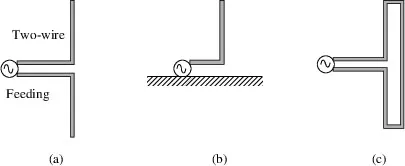
The simplest and most widely used antenna element is the half-wave dipole, which consists of two linear conductors about a quarter wave long, driven by a source at the center, as shown in Figure 1.1a. Two variations of the half-wave dipole are the quarter wave monopole (Figure 1.1b) and the folded dipole (Figure 1.1c).
Fig. 1.1 Illustrations of (a) dipole; (b) monopole and (c) folded dipole.
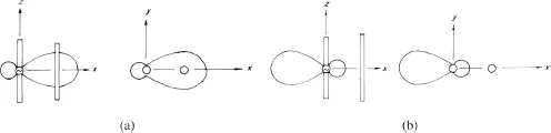
Fig. 1.2 (a) A driven element and a director; (b) a driven element and a reflector.
The pattern of a dipole can be modified by placing a passive or parasitic conductor near it. Although the parasitic element is not connected to a source, a current is induced in it due to the radiation from the driven dipole. The total radiation is the sum of the driven and the parasitic elements. By suitably choosing the length and spacing of the latter, it can act either as a reflector enhancing radiation in the direction of the dipole (negative x) or as a director enhancing radiation in its own direction (positive x). These are illustrated in Figure 1.2.
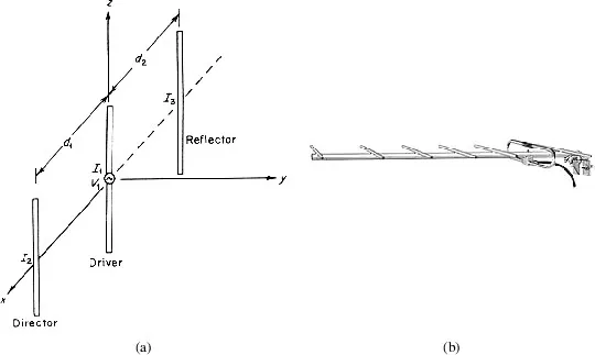
An antenna consisting of a driver, a reflecting element, and one or more directing elements is called a Uda-Yagi array or a Yagi for short (Figure 1.3). There is a limit to the number of parasitic elements that can be added to a Yagi since the induced current on a parasitic element becomes progressively smaller as its distance from the driven element increases. It ceases to play an effective role if it is placed too far from the driven element. Yagis are seldom designed to have more than 12 elements. A 7 element Yagi using a folded dipole as driver is shown in Figure 1.3b.
Fig. 1.3 (a) A three-element Yagi-antenna and (b) a seven-element Yagi-antenna using folded dipole as driver.
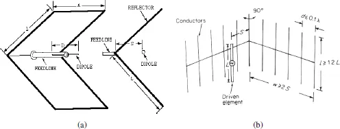
While a thin conductor can act as a reflector, it is highly sensitive to frequency. The frequency dependence is reduced if a plane conducting sheet is used instead. The effectiveness of the reflecting sheet can be further enhanced if it is bent into two sheets intersecting at an angle, as shown in Figure 1.4a. The resulting structure is known as a corner reflector antenna. The corner reflector has the limitation that, even if the sides are infinite in extent, there is an upper limit to the directivity of the resultant radiation. To reduce wind resistance, the reflecting metal sheets are replaced by conducting rods, resulting in a grid type corner reflector antenna (Figure 1.4b).
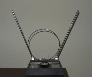
Other traditional antenna elements are the loop antenna, the horn antenna, and the helical antenna. The loop antenna is used extensively in TV reception and as directional finders. An indoor TV antenna consisting of a dipole and a loop is shown in Figure 1.5.
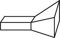
By flaring the aperture of an open-ended waveguide, a horn antenna is obtained (Figure 1.6). The horn antenna is used extensively at microwave frequencies, both as feed antennas for parabolic reflectors and as the standard calibration antenna for gain.
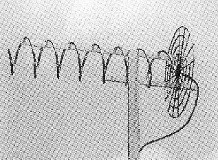
For communication with satellites and space vehicles, electromagnetic waves with circular polarization (CP) is preferred over linear polarization (LP). The helical antenna (Figure 1.7) is a popular CP antenna and was the antenna brought to the moon by the astronauts in the late 1960’s and early 1970’s.
Fig. 1.4 (a) Plane conductor type corner reflector antenna and (b) grid type corner reflector antenna.
Fig. 1.5 An indoor TV antenna.
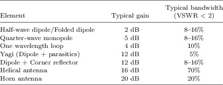
Two important antenna parameters are the gain and the impedance bandwidth. The gain describes the directional property of an antenna while the impedance bandwidth describes the range of frequencies within which the voltage standing wave ratio is below a certain value. This value is usually taken as 2 in academia and 1.5 in industry. The abbreviation for voltage standing wave ratio is VSWR or SWR. Both will be used in this book. Table 1.1 shows the typical values of these two parameters for the conventional antenna elements described above.
Fig. 1.6 A horn antenna.
Fig. 1.7 A helical antenna.
Table 1.1 Typical gain and bandwidth of conventional antenna elements.
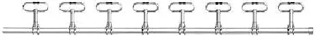
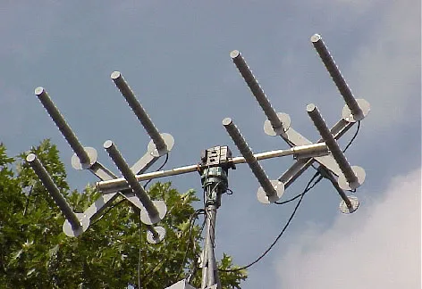
One method of obtaining high gain antennas is to use an array of fed elements, all of which are connected to a source. A linear array is one with the elements arranged in a straight line. The elements can also be arranged in a plane, resulting in a planar array. The element spacing is usually about half a wavelength. In theory, for a given spacing, the gain can be made as high as one wishes by increasing the number of elements. Figure 1.8 shows a linear array of folded dipoles. Photograph of a planar array of helical antennas is shown in Figure 1.9.
Fig. 1.8 A linear array of folded dipoles.
Fig. 1.9 A planar array of eight helical antennas. (Courtesy of SETI League).
Another method of obtaining high gain antennas is to use a parabolic reflector, with the feed antenna at the focus. This antenna is also known as a dish. For a given frequency, the gain is proportional to the diameter of the dish. In theory, the gain can be made as high as one wishes by increasing the dish diameter. Figure 1.10a shows the 1000 feet dish at the Arecibo Observatory in Puerto Rico. Figure 1.10b shows the 300 feet dish in Effelsberg, Germany. The former is the world’s largest dish but it is fixed on the ground, although the main beam can be steered to a limited extent by electronic means. The latter is one of the world’s largest fully steerable dishes. Figure 1.11 shows the Very Large Array (VLA) in New Mexico, consisting of 27 85-feet dishes arranged in the form of the letter Y.
Fig. 1.10 (a) The dish antenna at the Arecibo Observatory in Puerto Rico (Courtesy of Astronomy and Ionosphere Center); and (b) the dish antenna in Effelsberg, Germany (Courtesy of Max Planck Institute for Radio Astronomy).
Fig. 1.11 The Very Large Array (VLA) in New Mexico. (Courtesy of National Radio Astronomy Observatory).
Several undesirable features of the conventional antennas can be noted. They ...