![]()
Chapter 1
Digital Representation of Information
This chapter is focused on the ways computers represent information in digital format. In particular, it discusses the mechanisms used to represent various quantities in a digital computer. The digital electronic circuits that are commonly used in a digital computer can assume only one of two possible values, which implies that different quantities have to be represented in a format compatible with this restriction.
We will start by describing how integers are represented, both in the decimal number system, which is familiar to everybody and in other number systems more adequated to be manipulated by computers. In this chapter, this study is limited to non-negative integers and non-negative fractional numbers.
The chapter begins with Section 1.1, where we study binary, octal and hexadecimal number systems. Section 1.2 focuses on studying the foundations of binary arithmetic. Section 1.3 deals with the use of codes, both numeric (with emphasis on decimal codes) as well as alphanumeric (to represent other types of information). Section 1.4 concludes the chapter with some basic concepts on the organisation of binary representation of information.
1.1Number Systems
This chapter deals with the representation of non-signed integer and fractional numbers. Later, in Chapter 5, this subject will be reconsidered to address the representation of signed integer and real numbers. The representation of numbers in digital systems has to be undertaken considering that they use devices which can represent only two possible values.
Given that the common representation of numbers is based on the utilisation of a decimal number system, using base-10, it is natural to consider that the representation of numbers in digital systems may be made using the binary system, using base-2. The base is the number of digits used to represent a number under a given number system.
The general case of representation using a generic base-b will be studied first, followed by the study of the base-2 case.
1.1.1Representation of Integers in Base-b
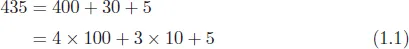
The representation of a non-signed integer in base-10 is made using a sequence of digits. The number 435, for example, is represented by the sequence of digits 4, 3 and 5. The interpretation of the representation of a number results, firstly, from the digits used and, secondly, from their position within the sequence. As is evident, 435 ≠ 354, even though the digits used are the same.
The position of the digits indicates the weight for each digit. In the previous example, because the digit 4 is in the third position from the right, this means, in fact, four hundreds. The digit 3 represents three tens, and 5 represents five units. This system of representation of numbers is referred as positional.
This analysis can be stated more formally as follows:
or, expressing the powers of 10 involved,
which is a more general way of representation, emphasising the powers of the base.
The number 435 is said to be represented in base-10 since it results from the sum of consecutive powers of 10, each multiplied by the value of the corresponding digit as shown in Equation (1.2). To explicitly indicate that the number is represented in base-10, the following notation is used: 43510. To represent a number in base-10, the weights of each power of 10 are indicated using digits from 0 to 9, using a total of 10 distinct digits.
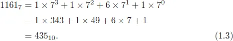
There is nothing to prevent the use of another base to represent a number. Consider, for example, the sequence of digits 1161 in base-7, which is usually indicated by 11617. In this case, this representation has the following meaning:
Therefore, 11617 is another way of representing the number 43510.
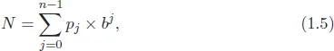
Generally speaking, any integer N can be represented in any base-b with b ≥ 2
or
where pj is the digit which represents the weight of the jth power of the base. The number of digits necessary is b and it is usual that the digits are the integers between 0 and b − 1
Thus, to represent numbers in base-b, digits of a value equal to or greater than b cannot be used. For example, the representation of a number in base-7 cannot use the digit 7 nor any other digit greater than 7. The sequence of digits 17427 is therefore not a valid representation of a number.
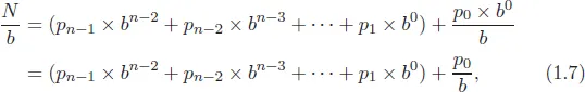
The conversion of the representation of a number in base-b to a representation in base-10 is not difficult, as illustrated by Equation (1.3). The reverse, converting a number represented in base-10 to its representation in base-b requires a little more work, but it is also simple. One of the most common methods is the method of successive divisions. As an example, consider a number N represented in base-b, as shown in Equation (1.4). If the number is divided by b, this results in
where p0 is the rest of the division of N by b (remember that p0 < b). In this way, the digit p0 can be identified.
Repeating the previous procedure for the number
will enable us to derive
p1 and through the successive application of the procedure, all the digits that represent the number.
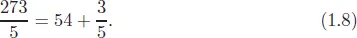
As an example, consider obtaining the representation of the number 27310 in base-5
In the same way, the following can be ...