![]()
Chapter 1
Aqueous Reprocessing of Used Nuclear Fuel
Jack D. Law
1. Introduction
Aqueous technologies for used nuclear fuel reprocessing have historically been utilized to recover uranium (U) and plutonium (Pu) from irradiated nuclear reactor fuel for recycle. The purpose for reprocessing used fuel has been to recover unused U and Pu in the used fuel elements. This results in gaining more energy from the original U and contributes to the national energy security of the country reprocessing their fuel. Also, reprocessing results in a reduction in volume of high-level waste for disposal, and the radiotoxicity is lower and reduces more rapidly than with used nuclear fuel.
With aqueous technologies, the used nuclear fuel is typically mechanically chopped into small pieces and leached into an acidic solution. The resulting dissolver product is chemically processed to separate actinides for recycle to a reactor. The remaining metals and fission products are treated for disposal as a high-level waste. The primary aqueous separation method utilized to accomplish the required separation is solvent extraction, although precipitation has been used initially in the US defense industry for the recovery of Pu for weapons.
The plutonium uranium reduction extraction (PUREX) process is the most common solvent extraction technology utilized in the USA and internationally for the separation of U and Pu from used nuclear fuel. Variations in the PUREX process are being developed and implemented to prevent the separation of pure Pu. Additionally, advanced aqueous separation technologies are being developed in the USA and internationally for the separation and recycle/transmutation of minor actinides.
2. Solvent Extraction
Solvent extraction is the primary technology utilized in aqueous used nuclear fuel reprocessing. First, used nuclear fuel from a reactor, after some amount of decay storage, is leached with an acidic solution. The resulting aqueous solution is separated from the remaining fuel cladding and then chemically processed via solvent extraction to separate the components of interest, typically U and/or Pu.
Solvent extraction within used nuclear fuel reprocessing utilizes an organic phase containing an extractant, in contact with the aqueous dissolver product via mixing, to extract the components of interest into the organic phase. Typically, this process is carried out by intimately mixing the two immiscible phases, allowing for the selective transfer of solute(s) from one phase to the other, then allowing the two phases to separate. The component of interest is subsequently removed from the organic phase to an aqueous phase via back-extraction. In order for effective processing, the two phases must be immiscible, have enough of a density difference to allow rapid disengagement, be of an appropriate viscosity to be transported through process equipment, limited solubility of the organic phase in the aqueous phase to maintain the extractant concentration over long-term use, and the organic phase must have sufficient hydrolytic and radiolytic stability to allow for long-term reuse to minimize organic waste volumes.
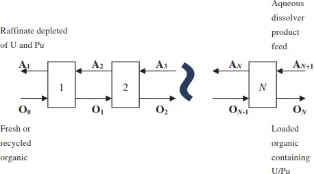
One of the primary advantages of solvent extraction processes is the ability to operate in a continuous, countercurrent manner with multiple contacting/separating stages to achieve the desired removal efficiency of the components being extracted. This allows for continuous operation instead of batch operation. Countercurrent operation is shown graphically for an extraction section of a U/Pu separation flowsheet in Figure 1.
In this flow diagram, the aqueous dissolver product feed stream containing the components to be extracted enters at one end of the process (AN+1), and the fresh solvent (organic) stream enters the other end (O0). The aqueous and organic steams flow countercurrently from stage to stage where they are intimately mixed and separated, and the final products are the solvent loaded with the desired components (e.g., U and Pu), ON, leaving stage N and the aqueous raffinate, A1, depleted in U and Pu leaving stage 1.
Figure 1. Countercurrent — Multistage extraction process flow diagram.
Following an extraction section, scrub, strip, and solvent wash sections are typically employed. The purpose of the scrub section is to back extract (scrub) to the extraction section any metals/fission products (e.g., Zr) that may have co-extracted along with the desired components. The strip section is utilized to back-extract the desired components (e.g., U and Pu) into an aqueous phase where they will ultimately be re-enriched and converted into an oxide form for recycle to a reactor, typically as MOX fuel. The solvent wash section is utilized to remove any hydrolytic or radiolytic degradation products from the solvent and prepare the solvent for recycle to the extraction section, thus minimizing organic waste volumes.
3. Solvent Extraction Equipment
Solvent extraction equipment has been utilized in the nuclear industry since the implementation of the PUREX process for the separation of Pu and U from fission products for weapons production in the 1950s [1]. This technology was later implemented for the reprocessing of used nuclear fuel from commercial power reactors. PUREX-based solvent extraction processing has been and continues to be utilized worldwide including France, Japan, Russia, the UK, and the USA. Additionally, considerable research in the development of advanced separation processes is ongoing, requiring the use of solvent extraction equipment. In these efforts, solvent extraction equipment is utilized to efficiently mix and separate the aqueous and organic phases to facilitate separation of the species of interest. The solvent extraction equipment is designed for countercurrent flow to facilitate high separation efficiencies and continuous operation.
To support operation in a radioactive environment, solvent extraction equipment must be remotely operable and maintainable, resistant to high radiation fields, capable of continuous countercurrent operation, and be critically safe for certain applications. In addition, desirable attributes include the ability to accommodate solids, a small process footprint, and operational flexibility (continuous long-term operation or frequent start–stop operation). The three main types of solvent extraction equipment used in industrial-scale reprocessing facilities and in fuel cycle research laboratories include (1) columns, (2) mixer-settlers, and (3) centrifugal contactors. A brief description of each type of equipment follows. More detailed description of these type of equipments can be found in literature [2, 3].
3.1. Columns
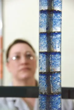
Packed columns and pulse columns with sieve plates or trays are the typical type of solvent extraction column utilized in the nuclear industry. Packed columns contain packing material (e.g., Raschig Rings) to create mixing of the two phases as they flow counter currently. The phases disengage at either the top or the bottom of the column depending upon whether the column is operated in an aqueous or organic continuous mode. Pulsed columns with trays or plates were developed to increase the mixing intensity of the phases and, thus, decrease the height requirement of the column. The mechanical energy applied to the column via pulsing with air facilitates the formation of small droplets for mass transfer. A photograph of an operating pulsed column used to support laboratory testing is shown in Figure 2.
3.2. Mixer-settlers
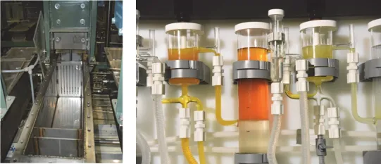
A mixer-settler contains a small mixing chamber and a larger settling chamber. The two immiscible phases enter the mixing chamber containing an impeller. This dispersion that forms flows into the settling chamber where the two phases separate by gravity. A system of weirs allow for the light phase to flow over the higher weir and the heavy phase to flow under the lower weir. Multiple mixer-settlers are configured for countercurrent flow to achieve high separation efficiency. A photo of several mixer-settlers is shown in Figure 3.
Figure 2. Operating lab-scale pulsed column at Idaho National Laboratory.
Figure 3. Industrial and lab-scale mixer-settlers.
3.3. Centrifugal contactors
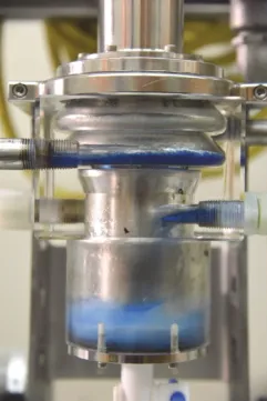
Centrifugal contactors consist of a hollow rotor that rotates within a cylindrical housing utilizing a motor mounted above the housing. The aqueous and organic feed solutions enter a stage near the top of the housing and are mixed as they flow downward. For annular centrifugal contactors, the shear forces between the spinning rotor and the stationary housing mix the two phases. Other contactor designs utilize alternative methods of mixing such as mixing pins attached to the bottom of the spinning rotor. When the mixture enters the spinning rotor through an opening at its base, the spinning rotor acts as a centrifuge with the heavy phase going to the rotor wall. A series of weirs allow the separated heavy and light phases to flow out of the contactors as separate streams. Multiple centrifugal contactors are configured for countercurrent flow to achieve high separation efficiency. An operating centrifugal contactor is shown in Figure 4.
Figure 4. Operating 5 cm centrifugal contactor with plastic housing.
4. Reprocessing History
Aqueous reprocessing technologies were first utilized at the Hanford Site during the Manhattan Project for the recovery of Pu-239 by using a bismuthate phosphate precipitation process [1]. Recovery transitioned to solvent extraction processes that allowed for continuous instead of batch operation, as well as the concurrent recovery of U and Pu. Also, the purpose of the reprocessing of used fuel transitioned from defense purposes to commercial use for the recycle of U and Pu.
The first solvent extraction process implemented was the reduction oxidation (REDOX) process [1]. The process was developed and tested at Argonne National Laboratory and Oak Ridge National Laboratory, and the first REDOX plant operated at Hanford. The REDOX process utilizes Methyl isobutyl ketone (hexone) to extract uranyl nitrate and Pu nitrate. U(VI) and Pu(IV) are co-extracted then the Pu is reduced to Pu(III) by using ferrous sulfamate and selectively stripped from the U. One disadvantage of this process is the required addition on aluminum nitrate to increase the nitrate concentration. Also, hexone is a flammable and volatile solvent.
The BUTEX process was developed by ...