![]()
Chapter 1
Basic Definitions and Logic Families
1.1.Basic definitions
Every physical process or event, every situation and condition, may be characterized numerically with the help of certain signals or quantities. These quantities may be observed, measured, manipulated, and stored (recorded). A quantity may be represented in analog and digital forms. Usually, all the signals existing in nature are analog or continuous values. Temperature, for example, changes continuously. The water level in a chemical reactor changes continuously also. If the signal varies continuously, we can say that its magnitude can take all possible values in the domain of the definition of the signal.
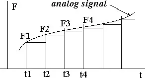
Analog signal processing can be performed by using different instruments. It can be performed by both analog and digital devices. However, to process an analog signal with a digital device, using a digital computer for example, we should convert the analog signal to digital form. To convert the signal we must measure it. We provide our measurements using existing measuring devices which have a defined accuracy. Moreover, we provide our measurements at defined intervals of time. An operation providing the analog–digital signal conversion is called sampling. Figure 1.1 illustrates this type of conversion. As shown in Fig. 1.1, an analog signal varies in time. We measure it at the points t1, t2... using a specific measurement device with suitable precision. All measured values F1, F2... are proportional to some minimal value called “unit,” which defines a range of approximation or a resolution of the device. The obtained quantity of measured units presents a numerical form of the measured signal which may be presented in one of the numerical digital scales, for example in the decimal or binary form.
Fig. 1.1.A sampling operation to convert the analog signal to a digital one.
This form is very convenient to process in digital computers. However, each numerical form always contains a systematic error. For example, we can always insert additional numbers between two neighbors. So, each signal may be presented in the analog as well as digital form. Now we can define the concepts of analog and digital signals:
•An analog value can have any level within certain operating limits, as long as it is proportional to the signal.
•A digital value can only have a number of fixed values within certain tolerance limits. Here, the quantity is represented by symbols called digits.
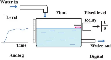
Figure 1.2 illustrates the principle of analog and digital signal measurement. On the left side of the picture, the analog type of measurement appears. The level of water in the tank changes continuously and we can draw a graphical representation of the water level as a function of processing time. On the right side, we can see the digital or discrete measurement system. The threshold of the water level is fixed. If a float comes into contact with the fixed contact representing the threshold, a relay will switch from the 0 state to the 1 state and will signal the level change. In this digital binary system, we can measure two levels: lower and higher.
Fig. 1.2.A simple measurement system.
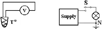
Fig. 1.3.Various measurement systems.
Figure 1.3 shows two additional examples of the measurement of different quantities.
In the picture on the left, a thermocouple (two different metals joined together) measures the temperature and transforms this natural parameter into voltage. All changes are continuous in the system; therefore, such a measuring system implements an analog device. In the picture on the right, a lamp shows the state of the switch “S.” If a supply is connected to the lamp by the switch, the lamp lights up and we can see that “S” is in the connected state. The switch “S” only has two different states. In other words, we can describe the action of this switch with two digits, 0 and 1. A digital system is one that processes a finite set of data in a digital (discrete) form. The signals may be represented in binary form or in a form that only has two operating states. These operating states, called logic states, may be of high (1) or low (0) logic levels. An electrical or electronic circuit implementing the possibility of obtaining two different logic levels opposite to the input level is called an inverter. An inverter is a minimal logic gate. So, a logic gate is a standard electronic scheme implementing some logic operation, logic sum or logic multiplication, for example.
The digital system that may be in different logic states is called the logic system. Every logic system may be represented by a finite number of discrete elements. For example, the Hebrew language consists of 22 letters, English has 26 letters, and Russian has 33 letters. However, each of them can put into words all the nuances and inflections of human sensations and thoughts. Thus, each logic system may be implemented in numerous different ways. The next example is as follows: ten decimal digits permit the creation of mathematics... Two or three digits permit the creation of mathematics also. So, one can say that the discrete appearance of the natural analog function is ambiguous; there are a multitude of right solutions for digital logic systems. We will see further that various logic systems or electronic schemes may implement the same logic function. The art of logic design consists of the knowledge of all the methods and techniques and the ability to apply them to create the optimal solution. What criterion of the optimization, it will be clear from specific conditions. That may be a cost of devices, or processing rate, or some other reasons.
A logic system consists of logic devices. A connection of two simple logic devices is presented in Fig. 1.4.
A logic system may be loaded by a few logic gates. Logic gates may be created using various technologies: diodes, bipolar transistors, MOS transistors. They may be electronic or pneumatic devices. Usually, logic gates from the same family of devices are used for the creation of complex logic systems. Figure 1.5 illustrates a connection of the same logic gates in one more complex system. A fan-out is the number of logic gates connected...