Digital Systems Design, Volume III
eBook - ePub

Digital Systems Design, Volume III

Latch–Flip-Flop Circuits and Characteristics of Digital Circuits

  1. 196 pages
  2. English
  3. ePUB (mobile friendly)
  4. Available on iOS & Android
eBook - ePub

Digital Systems Design, Volume III

Latch–Flip-Flop Circuits and Characteristics of Digital Circuits

About this book

Working as an engineer with advanced weapon systems for more than 25 years, it was crucial to understand the fundamentals of digital systems design development methods and combinational logic circuits. Whether as a technician or as an engineer, these fundamentals are the basics of engineering and are essential in interpreting logic gate functionality. The intent of this book is to provide much more information than most commercial engineering references currently offer.

Chapter 1, Latch and Flip Flop Circuits, discusses fundamental operations of NAND gate latch, NOR gate latch, gated S-C latch, gated D latch, four-bit bistable latch, D-type flip flop, JK-type flip flop, and master slave JK-type flip flop circuits. Chapter 2, Characteristics of Digital Circuits, provides a brief introduction to circuit characteristics. This chapter discusses RC time constants, electrical and dynamic behavior of circuits, timing considerations, and data storage and transfer devices. The chapter review and answer sections contain an extensive number of questions that afford comprehensive insights into obtaining the answers. This book will be an extremely valuable asset for technical and engineering students studying digital system design.

Frequently asked questions

Yes, you can cancel anytime from the Subscription tab in your account settings on the Perlego website. Your subscription will stay active until the end of your current billing period. Learn how to cancel your subscription.
At the moment all of our mobile-responsive ePub books are available to download via the app. Most of our PDFs are also available to download and we're working on making the final remaining ones downloadable now. Learn more here.
Perlego offers two plans: Essential and Complete
  • Essential is ideal for learners and professionals who enjoy exploring a wide range of subjects. Access the Essential Library with 800,000+ trusted titles and best-sellers across business, personal growth, and the humanities. Includes unlimited reading time and Standard Read Aloud voice.
  • Complete: Perfect for advanced learners and researchers needing full, unrestricted access. Unlock 1.4M+ books across hundreds of subjects, including academic and specialized titles. The Complete Plan also includes advanced features like Premium Read Aloud and Research Assistant.
Both plans are available with monthly, semester, or annual billing cycles.
We are an online textbook subscription service, where you can get access to an entire online library for less than the price of a single book per month. With over 1 million books across 1000+ topics, we’ve got you covered! Learn more here.
Look out for the read-aloud symbol on your next book to see if you can listen to it. The read-aloud tool reads text aloud for you, highlighting the text as it is being read. You can pause it, speed it up and slow it down. Learn more here.
Yes! You can use the Perlego app on both iOS or Android devices to read anytime, anywhere — even offline. Perfect for commutes or when you’re on the go.
Please note we cannot support devices running on iOS 13 and Android 7 or earlier. Learn more about using the app.
Yes, you can access Digital Systems Design, Volume III by Larry Massengale in PDF and/or ePUB format, as well as other popular books in Technology & Engineering & Electrical Engineering & Telecommunications. We have over one million books available in our catalogue for you to explore.

CHAPTER 1

LATCH AND FLIP FLOP CIRCUITS

1.1. INTRODUCTION

In Volume II Chapter 3 we discussed combinational logic circuits whose outputs depended upon their inputs. These inputs and outputs cannot retain their logic levels for future storage capability further operations. Unlike combinational logic circuits, several digital system circuits have the ability to store data, which requires memory capacity. These circuits are referred to as sequential logic circuits and depend on their previous and current state inputs. Their outputs will be tied back to their inputs in some respect, providing the necessary feedback of their circuits. Latch and flip flop circuits are these types of digital circuits. The latch circuit forms the basic core for the foundation of flip flops. In this chapter we will learn about the different types of latch and flip flop circuits.
Additionally, it is critical to understand that Transistor-Transistor Logic (TTL) and Complementary Medal-Oxide Semiconductor (CMOS) devices have special characteristics to prevent design flaws and damage to chips. Many of the electrical behaviors with discrete circuits also apply to these materials. These special characteristics will also be discussed in this chapter.

1.2. ACTIVE LOW LATCH—NAND GATE LATCH

The active low latch has two inputs, identified as SET′ and CLR′, hence active low latch. The latch outputs are Q and Q′. Figure 1.1 shows how one NAND gate output feeds back to the other NAND gate input with opposite polarity, the state of each input combination, the logic symbol for the active low latch, and the active low latch waveform.
Figure 1.1. Active low latch logic diagrams and state table
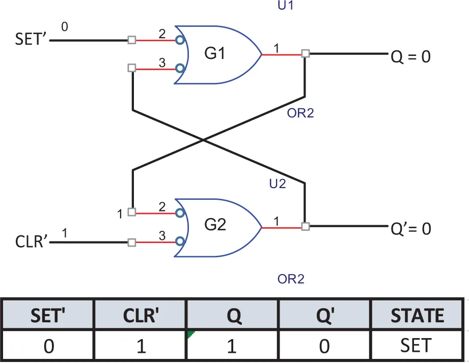
Gate latch SET′ and CLR′ level will be explained next. As shown in Figures 1.2 to 1.5, the completed aforementioned active low latch state table is analyzed. We began with SET′ = 0 and CLR′ = 1, as shown in Figure 1.2, where the output of logic gate G1 is a logic high or 1. This logic 1 is feedback from the output of gate G1 to the top input of logic gate G2. This input logic 1 along with the CLR′ logic 1 will produce a logic low or logic 0 output to logic gate G2. When the SET′ = 0 and CLR′ = 1 inputs exist, this condition places the active low latch in a SET state as shown in the state table in Figure 1.2.
Figure 1.2. SET state of the active low latch
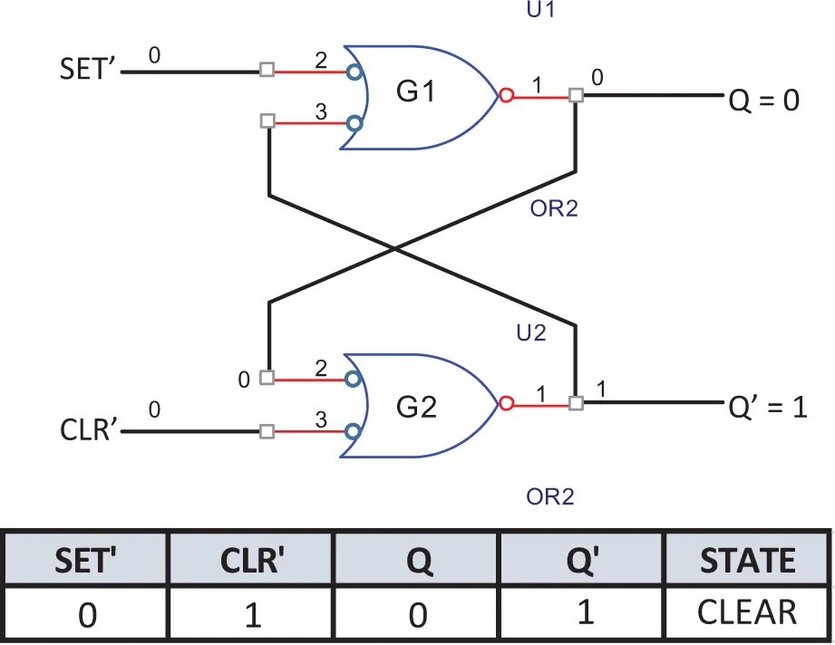
Next we show SET′ = 1 and CLR′ = 0 in Figure 1.3, where the output of logic gate G1 is a logic low or logic 0. This logic 0 is feedback from the output of gate G1 to the top input of logic gate G2. This input logic 0 along with the CLR′ logic 0 will produce a logic high or logic 1 output to logic gate G2. When the SET′ = 1 and CLR′ = 0 inputs exist, this condition places the active low latch in a CLEAR state as shown in the state table in Figure 1.3.
Figure 1.3. CLEAR state of the active low latch
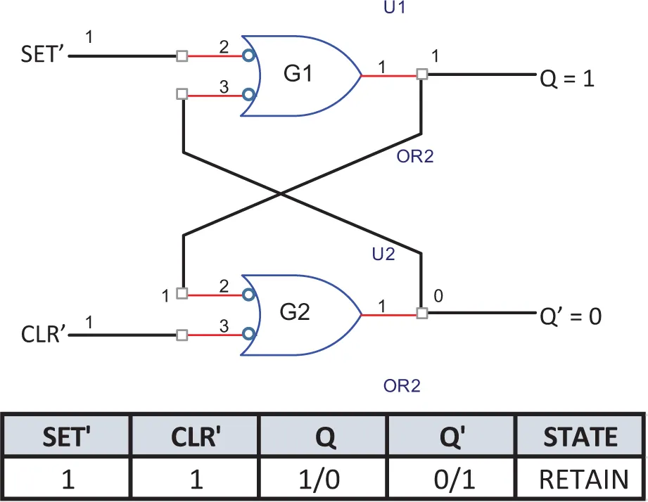
Next we show SET′ = 1 and CLR′ = 1. In Figure 1.4, we assume that the latch circuit is in the SET state where Q = 1 and Q′ = 0. We can assume that the circuit is either in the SET or the CLEAR state. In order to explain our current input condition of SET′ = CLEAR = 1, we simple trace back from the Q′= 0 output to the lower input to gate G1. The low input causes gate G1′s output to retain a logic 1 output. When tracking back from the logic 1 G1 output to the upper G2 input we have two logic 1 inputs causing the Q′ output of a logic 0. When both circuit inputs are high or logic 1 the latch will retain the state it was in previously. We can analyze both SET and CLEAR states of the latch circuit and determine that the latch will be in the RETAINed state. Figure 1.4 shows the RETAIN state of the previous latch state—the previous SET state in our example.
Figure 1.4. RETAIN state of the a...

Table of contents

  1. Cover
  2. Half Title
  3. Title Page
  4. Copyright Page
  5. Contents
  6. List of Figures
  7. List of Tables
  8. Acknowledgments
  9. Chapter 1 Latch and Flip Flop Circuits
  10. Chapter 2 Characteristics of Digital Circuits
  11. Bibliography
  12. About the Author
  13. Index