Radome Electromagnetic Theory and Design explores the theoretical tools and methods required to design radomes that are fully transparent to the electromagnetic energy transmitted or received by the enclosed antenna. A radome is a weatherproof and camouflaged enclosure that protects the enclosed radar or communication antenna, and are typically used on a fixed or moving platform such as an aircraft, ship or missile.
The author — a noted expert in the field — examines the theoretical methods that apply to all type of radomes: planar, conformal, airborne and ground based. The text offers a description of the various measurement methods that characterise the electrical parameters of a radome, and discusses their merits in terms of accuracy. This groundbreaking book brings together in one volume all the necessary theoretical tools to design radomes
Trusted by 375,005 students
Access to over 1.5 million titles for a fair monthly price.
The word radome, is an acronym of two words “radar” and “dome” and is a structural, weatherproof enclosure that protects the enclosed radar or communication antenna. The main objective of the radome is to be fully transparent to the electromagnetic energy transmitted/received by the enclosed antenna, and in this sense its objective is similar to that of a glass window for light in the optics spectrum. Radomes protect the antenna surfaces from weather and, in contrast to a glass window, can also conceal the antenna electronic equipment from the outside radome observer. Another benefit for using a radome is that it enables use of a low-power antenna rotating systems and weaker antenna mechanical design, followed by a significant price reduction, since the enclosed antenna is not exposed to the harsh outside weather. Radomes can be constructed in several shapes (spherical, geodesic, planar, etc.), depending on the particular application using various construction materials (e.g., fiberglass, quartz, polytetrafluoroethylene (PTFE)-coated fabric, closed cell foam (rohacell), honeycomb). The radomes are assembled on aircrafts, ships, cars, and in fixed ground-based installations. In case of high-speed moving platforms like aircrafts, another important consideration is related to the streamline shape of the radome to reduce its drag force.
The materials used to construct radomes are often used to prevent ice and freezing rain (sleet) from accumulating directly on its external surface to avoid extra losses of the communication link. In case of a spinning radar dish antenna, the radome also protects the antenna from debris and rotational problems due to wind. For stationary antennas, excessive ice accumulation on the radome surface can de-tune the antenna, causing extra losses and internal reflections, which may go back to the transmitter and cause overheating. A good designed radome prevents that from happening by covering the exposed parts with a sturdy' weatherproof material like PTFE, which keeps debris or ice away from the antenna. One of the main driving forces behind the development of fiberglass as a structural material was the need for radomes during World War II. Sometimes radomes may be internally heated to melt the accumulated ice on their exterior surface. The most common shape of ground-based radomes is spherical because of the rotational symmetry such a radome offers. Large ground-based radomes are made of sandwich panels interconnected by seams or beams, which may affect the enclosed antenna radiation pattern as described in Chapter 6. Small or medium-sized radomes are usually made of one molded piece. In this case, only the transmission loss and boresight error caused by the radome need to be considered in the design as explained in Chapter 4.
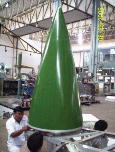
figure 1.1 Tejas aircraft (India) radome picture.
Static electricity caused by air friction on the radome surface can present a serious shock hazard. Thin antistatic coatings are used to neutralize static charge by providing a conducting path to attached structures. Lightning strikes to aircraft are common, so metallic lightning-diverter strips are used to minimize structural damage to the radome. Diverters cause some increase in sidelobe levels; this effect can be estimated using the computational tools described in Chapter 5.
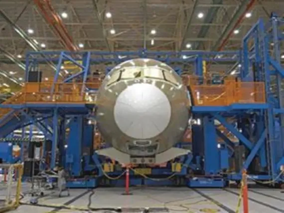
The US Air Force Aerospace Defense Command operated and maintained dozens of air defense radar stations in the United States, including Alaska, during the Cold War. Most of the radars used at these ground stations were protected by rigid or inflatable radomes. The radomes were typically at least 15 m (50 ft) in diameter, and the radomes were attached to standardized radar tower buildings that housed the radar transmitter, receiver, and antenna. Some of these radomes were very large. The CW-620 was a rigid space frame radome with a maximum diameter of 46 m (150 ft), and a height of 26 m (84 ft). This radome consisted of 590 panels and was designed for winds of up to 240 km/h (150 mph). The total radome weight was 92,700 kg (204,400 lb) with a surface area of 3680 m2 (39,600 ft2). The CW-620 radome was designed and constructed by Sperry-Rand Corp. for the Columbus Division of the North American Aviation. This radome was originally used for the FPS-35 search radar at Baker Air Force Station in Oregon. Two typical airborne radomes are shown in Fig. 1.2 and Fig. 1.1. Both of them are ogive type, but with different contours.
figure 1.2 Norton radome B787 dreamliner picture.
For maritime satellite communication service, radomes are widely used to protect dish antennas, which are continually tracking fixed satellites while the ship experiences pitch, roll, and yaw movements. Large cruise ships and oil tankers may have radomes over 3 m in diameter covering antennas for broadband transmissions for television, voice, data, and the internet, while recent developments allow similar services from smaller installations, such as the 85 cm motorized dish used in the ASTRA2 Connect Maritime Broadband system. Small private yachts may use radomes as small as 26 cm in diameter for voice and low-speed data transmission/reception.
1.1 History of Radome Development
The first radomes appeared in United States in 1940 with the introduction of the radar during the World War II when radars were installed on aircrafts and aerodynamics considerations were imposed to cover the radar antennas to reduce the drag forces on a high speed aircraft. The first reported aircraft radomes used simple, thin-wall designs. In 1941, the first in-flight radome was a hemispherical nose radome fabricated from plexiglass [1, 2]. It protected an experimental S-band, Western Electric radar flown in a B-18A aircraft. Beginning 1943, production airborne radars used plywood radomes [1].
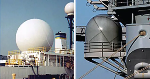
In this period, plywood radomes also appeared on Navy PT boats and blimps, as well as in ground installations. Because plywood has moisture absorption problems and does not easily bend into doubly curved shapes, new radome construction techniques and materials were introduced. In 1944, the MIT Radiation Laboratory developed the three-layer A-sandwich, which used dense skins and a low-density core material. The skins were fabricated from fiberglass and the core from polystyrene. Since World War II, radome materials have developed in the following areas: ceramics for high-speed missile radomes, quartz, fiberglass, honeycomb, and foam for sandwich composites radomes. Today, the majority of aircraft radomes use sandwich-wall designs. Fig. 1.3 shows some typical radomes installed on ships.
figure 1.3 Typical radomes installed on ships.
Various authors have contributed to the literature describing the evolution, design, and manufacture of radomes. Cady [3] describes the electrical design of normal and streamlined radomes and their installation, together with the theory of reflection and ...
Table of contents
Cover
Title Page
Copyright
Dedication
Table of Contents
Preface
Acknowledgments
Chapter 1: Introduction
Chapter 2: Sandwich Radomes
Chapter 3: Frequency Selective Surfaces (FSS) Radomes
Chapter 4: Airborne Radomes
Chapter 5: Scattering from Infinite Cylinders
Chapter 6: Ground-Based Radomes
Chapter 7: Measurement Methods
Appendices A Vector AnalysisAppen
Appendices B Dielectric Constants and Loss Tangent for Some Radome Materials
Appendices C Basic Antenna Theory
Index
End User License Agreement
Frequently asked questions
Yes, you can cancel anytime from the Subscription tab in your account settings on the Perlego website. Your subscription will stay active until the end of your current billing period. Learn how to cancel your subscription
No, books cannot be downloaded as external files, such as PDFs, for use outside of Perlego. However, you can download books within the Perlego app for offline reading on mobile or tablet. Learn how to download books offline
Perlego offers two plans: Essential and Complete
Essential is ideal for learners and professionals who enjoy exploring a wide range of subjects. Access the Essential Library with 800,000+ trusted titles and best-sellers across business, personal growth, and the humanities. Includes unlimited reading time and Standard Read Aloud voice.
Complete: Perfect for advanced learners and researchers needing full, unrestricted access. Unlock 1.5M+ books across hundreds of subjects, including academic and specialized titles. The Complete Plan also includes advanced features like Premium Read Aloud and Research Assistant.
Both plans are available with monthly, semester, or annual billing cycles.
We are an online textbook subscription service, where you can get access to an entire online library for less than the price of a single book per month. With over 1.5 million books across 990+ topics, we’ve got you covered! Learn about our mission
Look out for the read-aloud symbol on your next book to see if you can listen to it. The read-aloud tool reads text aloud for you, highlighting the text as it is being read. You can pause it, speed it up and slow it down. Learn more about Read Aloud
Yes! You can use the Perlego app on both iOS and Android devices to read anytime, anywhere — even offline. Perfect for commutes or when you’re on the go. Please note we cannot support devices running on iOS 13 and Android 7 or earlier. Learn more about using the app
Yes, you can access Radome Electromagnetic Theory and Design by Reuven Shavit in PDF and/or ePUB format, as well as other popular books in Technology & Engineering & Electrical Engineering & Telecommunications. We have over 1.5 million books available in our catalogue for you to explore.