Piping and Instrumentation Diagram Development
eBook - ePub

Piping and Instrumentation Diagram Development

Moe Toghraei

Share book
  1. English
  2. ePUB (mobile friendly)
  3. Available on iOS & Android
eBook - ePub

Piping and Instrumentation Diagram Development

Moe Toghraei

Book details
Book preview
Table of contents
Citations

About This Book

An essential guide for developing and interpreting piping and instrumentation drawings

Piping and Instrumentation Diagram Development is an important resource that offers the fundamental information needed for designers of process plants as well as a guide for other interested professionals. The author offers a proven, systemic approach to present the concepts of P&ID development which previously were deemed to be graspable only during practicing and not through training.

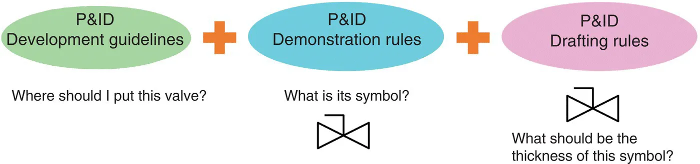
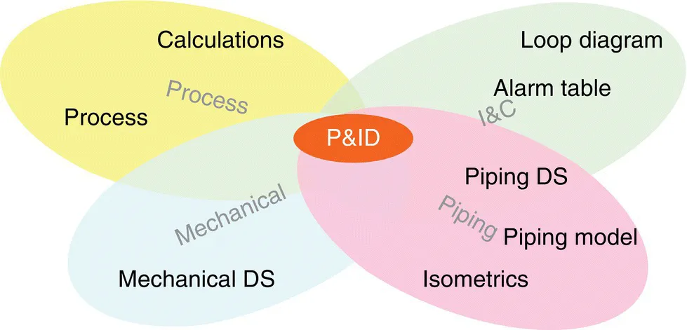
This comprehensive text offers the information needed in order to create P&ID for a variety of chemical industries such as: oil and gas industries; water and wastewater treatment industries; and food industries. The author outlines the basic development rules of piping and instrumentation diagram (P&ID) and describes in detail the three main components of a process plant: equipment and other process items, control system, and utility system. Each step of the way, the text explores the skills needed to excel at P&ID, includes a wealth of illustrative examples, and describes the most effective practices.

This vital resource:

  • Offers a comprehensive resource that outlines a step-by-step guide for developing piping and instrumentation diagrams
  • Includes helpful learning objectives and problem sets that are based on real-life examples
  • Provides a wide range of original engineering flow drawing (P&ID) samples
  • Includes PDF's that contain notes explaining the reason for each piece on a P&ID and additional samples to help the reader create their own P&IDs

Written for chemical engineers, mechanical engineers and other technical practitioners, Piping and Instrumentation Diagram Development reveals the fundamental steps needed for creating accurate blueprints that are the key elements for the design, operation, and maintenance of process industries.

Frequently asked questions

How do I cancel my subscription?
Simply head over to the account section in settings and click on “Cancel Subscription” - it’s as simple as that. After you cancel, your membership will stay active for the remainder of the time you’ve paid for. Learn more here.
Can/how do I download books?
At the moment all of our mobile-responsive ePub books are available to download via the app. Most of our PDFs are also available to download and we're working on making the final remaining ones downloadable now. Learn more here.
What is the difference between the pricing plans?
Both plans give you full access to the library and all of Perlego’s features. The only differences are the price and subscription period: With the annual plan you’ll save around 30% compared to 12 months on the monthly plan.
What is Perlego?
We are an online textbook subscription service, where you can get access to an entire online library for less than the price of a single book per month. With over 1 million books across 1000+ topics, we’ve got you covered! Learn more here.
Do you support text-to-speech?
Look out for the read-aloud symbol on your next book to see if you can listen to it. The read-aloud tool reads text aloud for you, highlighting the text as it is being read. You can pause it, speed it up and slow it down. Learn more here.
Is Piping and Instrumentation Diagram Development an online PDF/ePUB?
Yes, you can access Piping and Instrumentation Diagram Development by Moe Toghraei in PDF and/or ePUB format, as well as other popular books in Technology & Engineering & Chemical & Biochemical Engineering. We have over one million books available in our catalogue for you to explore.

Information

Part I
Fundamentals of P&ID Development

In part 1 we are going to cover the common rules of P&ID development. This part has five chapters:
Chapter 1: What is P&ID?
Chapter 2: Management of P&ID development
Chapter 3: Anatomy of a P&ID sheet
Chapter 4: General rules in drawing P&IDs
Chapter 5: Principles of P&ID development
In Chapter 1 we will cover the identification of P&ID and its role in process industries.
Chapter 2 covers the progress steps of P&ID during a design project.
Chapter 3 talk about different components of a P&ID sheet and their meaning.
Chapters 4 and 5 cover some rules and guidelines about P&IDs. In the world of P&IDs there would be at least three sets of rules, guidelines or standards.
image
An example is a valve. The engineer should decide if they need to put the valve in that specific location or not, and if needed, which type of valve with which type of actuator should be used.
The engineer uses “P&ID development rules.”
In the second step, when it is decided to put a manual gate valve, the question is how to show it. The engineer and the drafter together agree on a specific symbol based on “P&ID demonstration rules.”
image
As it was mentioned before, we are not going to talk about drafting rules. Chapter 4 covers demonstration rules and Chapter 5 explains the general guidelines about P&ID development.

1
What Is P&ID

1.1 Why Is P&ID Important?

The piping and instrumentation diagram (P&ID) is what might be considered the bible of a chemical process plant (CPI). It provides a lot of information for the manufacturing of the equipment, installation, commissioning, start‐up, and the operation of a plant. It also presents how a process plant should handle emergency situations.
The P&ID is a frequently referenced document throughout a project term – from the designing stages to the plant‐in‐operation phase – by various engineering disciplines, in technical meetings with vendors or manufacturers, hazard and operability study (HAZOP) meetings, management meetings, and project scheduling and planning. It is also one of the few documents created by multiple engineering groups such as Process, Instrumentation and Control (I&C), Plot plant and Piping (PL&P), Mechanical, Heat Ventilation and Air Conditioning(HVAC), and to a lesser extent Civil, Structural, and Architecture(CSA) and environmental or regulatory groups.
The information provided by the P&ID allows for the generation of other documents, including piping isometric drawings, the piping model, equipment and instrument lists, cause‐and‐effect diagrams, control philosophy, alarm set‐point tables, line designation table (LDT) or line list, material take‐offs, loop diagrams, tie‐in lists, and many more (Figure 1.1). The P&ID can ironically be considered an acronym for “primary interdisciplinary document.”
Image described by caption and surrounding text.
Figure 1.1 The P&ID is used by other groups to prepare other project documents.
All the abovementioned groups involved in a process plant should be familiar with P&IDs to some extent. P&IDs can be considered the source document to prepare “shopping lists” for piping, mechanical, and I&C requirements.
Process and I&C groups should be fully knowledgeable about P&IDs because they are the main developers of P&IDs, together with Mechanical and Electrical groups who can also provide some input during development such as the equipment list from mechanical engineers and motor list and electrical classification list from electrical engineers. I&C practitioners should be familiar with the P&IDs because from it they develop their instrument list, I/O list (a document listing instrumentation which serves as an input or output of the control system), and so on. The Piping group should be familiar with P&ID because it is their main working document and they need this to develop their piping model and piping isometric drawings. Civil engineers should also know P&IDs, although to a lesser extent. However, if the materials are concrete, like in large wastewater treatment plants, they should be familiar with P&IDs....

Table of contents