Electrical Systems for Nuclear Power Plants
eBook - ePub

Electrical Systems for Nuclear Power Plants

  1. English
  2. ePUB (mobile friendly)
  3. Available on iOS & Android
eBook - ePub

Electrical Systems for Nuclear Power Plants

About this book

Covers all aspects of electrical systems for nuclear power plants written by an authority in the field

Based on author Omar Mazzoni's notes for a graduate level course he taught in Electrical Engineering, this book discusses all aspects of electrical systems for nuclear power plants, making reference to IEEE nuclear standards and regulatory documents. It covers such important topics as the requirements for equipment qualification, acceptance testing, periodic surveillance, and operational issues. It also provides excellent guidance for students in understanding the basis of nuclear plant electrical systems, the industry standards that are applicable, and the Nuclear Regulatory Commission's rules for designing and operating nuclear plants.

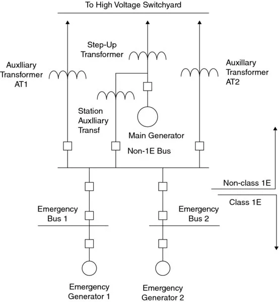
Electrical Systems for Nuclear Power Plants offers in-depth chapters covering: elements of a power system; special regulations and requirements; unique requirements of a Class 1E power system; nuclear plants containment electrical penetration assemblies; on-site emergency AC sources; on-site emergency DC sources; protective relaying; interface of the nuclear plant with the grid; station blackout (SBO) issues and regulations; review of electric power calculations; equipment aging and decommissioning; and electrical and control systems inspections. This valuable resource:

  • Evaluates industry standards and their relationship to federal regulations
  • Discusses Class 1E equipment, emergency generation, the single failure criterion, plant life, and plant inspection
  • Includes exercise problems for each chapter

Electrical Systems for Nuclear Power Plants is an ideal text for instructors and students in electrical power courses, as well as for engineers active in operating nuclear power plants.

Frequently asked questions

Yes, you can cancel anytime from the Subscription tab in your account settings on the Perlego website. Your subscription will stay active until the end of your current billing period. Learn how to cancel your subscription.
At the moment all of our mobile-responsive ePub books are available to download via the app. Most of our PDFs are also available to download and we're working on making the final remaining ones downloadable now. Learn more here.
Perlego offers two plans: Essential and Complete
  • Essential is ideal for learners and professionals who enjoy exploring a wide range of subjects. Access the Essential Library with 800,000+ trusted titles and best-sellers across business, personal growth, and the humanities. Includes unlimited reading time and Standard Read Aloud voice.
  • Complete: Perfect for advanced learners and researchers needing full, unrestricted access. Unlock 1.4M+ books across hundreds of subjects, including academic and specialized titles. The Complete Plan also includes advanced features like Premium Read Aloud and Research Assistant.
Both plans are available with monthly, semester, or annual billing cycles.
We are an online textbook subscription service, where you can get access to an entire online library for less than the price of a single book per month. With over 1 million books across 1000+ topics, we’ve got you covered! Learn more here.
Look out for the read-aloud symbol on your next book to see if you can listen to it. The read-aloud tool reads text aloud for you, highlighting the text as it is being read. You can pause it, speed it up and slow it down. Learn more here.
Yes! You can use the Perlego app on both iOS or Android devices to read anytime, anywhere — even offline. Perfect for commutes or when you’re on the go.
Please note we cannot support devices running on iOS 13 and Android 7 or earlier. Learn more about using the app.
Yes, you can access Electrical Systems for Nuclear Power Plants by Dr. Omar S. Mazzoni in PDF and/or ePUB format, as well as other popular books in Physical Sciences & Energy. We have over one million books available in our catalogue for you to explore.

Information

1
Elements of a Power System

This chapter discusses the main elements of a power system that are particularly applicable to understanding the basic electrical configuration of a nuclear power plant.

1.1 The Alternating Current One-Line Diagram

A useful diagram to depict the alternating current (ac) system of a nuclear generating station is the one-line diagram (OLD) [6]. The OLD allows for the simplest representation of the main elements of a typical station and the interconnections among them. Figure 1.1 depicts a typical OLD for the high voltage and the medium voltage portions of a nuclear power station. Depending on the plant design and year of start of operations, the OLD may be somewhat different than the one depicted in Figure 1.1. The OLD of Figure 1.1 depicts a preferred approach to nuclear station design, as it offers enhanced independence for the safety-related busses.
Diagram shows nuclear station which includes elements like emergency generators, emergency buses, class 1E bus, non-class 1E bus, auxiliary transformers, main generator, step-up transformer, and buses to high voltage switchyard.
Figure 1.1 One-line diagram of nuclear station.
While transformers AT1 and AT2 can be connected to the safety buses and also to the nonsafety buses, they are mainly intended to feed the safety-related busses. The only time that AT1 and AT2 are used to supply the plant nonsafety-related loads is for plant start-up or shutdown.
The plant normal operating conditions are with transformer AT feeding the plant nonsafety-related loads. Transformers AT1 and AT2 and normally energized and feed the safety buses, with both of these transformers being assigned to the two safety-related buses. Each one of the safety-related buses can be fed from an emergency diesel generator (EDG). Under normal plant operation, the EDGs are on standby condition.
After the generator starts up and synchronized to the grid, it is initially loaded with grid load to about 30% normal plant load, at which time the secondary side breakers of transformer AT are closed to feed the plant auxiliary loads.
The preferred mode of starting up the station would be by synchronizing across the generator circuit breaker and feeding the station auxiliaries through transformer AT. An alternate approach, though less preferred, would be through either transformer AT1 or AT2, which would require a bus transfer to eventually feed plant loads through transformer AT.
Automatic bus transfers are necessary to prevent paralleling of two sources, which would impose undue short circuit stresses for the circuit breakers.
Thorough the plant start-up process, the two safety-related buses remain energized and are not subjected to any transfer operations, thereby eliminating the possibility of transients to be induced in the safety system.
The plant design allows for the possibility of testing the EDGs as required by the plant surveillance. The EDGs are tested once a month, and loads are picked up from the system for the period of test duration.

1.2 Basis for One-Line Representation

For a three-phase power system, in order properly represent it in an OLD, the system must be balanced, that is each one of the three phases must carry the same magnitude of current, and the currents must be at 120° from each other. As a result, the balanced three-phase system may be represented by just one of its phases, as they are the same to each other.

Percent and Per Unit Representation

In the definition of electrical power system values, a representation in percent (%) or per unit (pu) is more convenient than actual units such as ohm, volts, etc,
A base value must be introduced to show quantities in percent or per unit. For example, assuming a base voltage of 4.16 kV:
  • 4.0 kV becomes 0.9615 pu, 96.15%
  • 7.2 kV becomes 1.73 pu, 173%
The pu system is preferred because the product of two pu values results in pu, whereas the product of two percent values must be divided by 100 to express the result in percent.
Two base values must be selected to have all other values automatically determined. Generally, kVA and kV are selected. The term MVA refers to MVA for three phase and the term kV to voltage from line to line, then the term current refers to line current. Generally, power is understood to be three-phase power and voltage the line-to-line voltage, unless otherwise specified. A major exception occurs in the method of symmetrical components, where line-to-neutral voltage is used.
Per unit and percent values of transformer impedances are the same on either side of the unit (primary or secondary). Also, the per unit and percent values do not depend on the transformer connections (wye–wye, delta–wye…etc.)
The following relationships apply (see [8]):
  • Base current, A = base kVA/1.732 base kV
  • Ω = (base voltage, kVLN)2/base MVA
  • Base impedance, Ω = (base voltage, kVLN)2/base MVA
  • Per unit impedance = actual impedance, Ω/base impedance, Ω
When dealing with unbalanced systems, symmetrical components must be used. In this method, the sequence components are always line to neutral or line to ground, as appropriate.

1.3 Main Electrical Components of Power Plants

Rotating Machines

Generators

Two types of generators are found in nuclear power plants: main generators that convert the mechanical power into electrical power and emergency standby generators utilized to provide electrical power to safety-related equipment when the normal power is not available [5,7]. This course places particular emphasis on the review of requirements for standby generators, as they are intrinsically involved in the performance of safety-related functions.

Motors

Most motors encountered in safety-related systems for nuclear power plants are of the AC induction type, constant speed. Some plants have AC var...

Table of contents

  1. Cover
  2. Titlepage
  3. Copyright
  4. Preface
  5. 1 Elements of a Power System
  6. 2 Nuclear Power Plants: General Information
  7. 3 Special Regulations and Requirements
  8. 4 Unique Requirements: Class 1E Power System
  9. 5 Nuclear Plants Containment Electrical Penetration Assemblies
  10. 6 On-Site Emergency Alternating Current Source
  11. 7 On-Site Emergency Direct Current Source
  12. 8 Protective Relaying
  13. 9 Interface of the Nuclear Plant with the Grid
  14. 10 Station Blackout: Issues and Regulations
  15. 11 Review of Electric Power Calculations
  16. 12 Plant Life: Equipment Aging, Life Extension, and Decommissioning
  17. 13 Electrical and Control Systems Inspections
  18. Appendix 1 Abbreviations
  19. Appendix 2 Definitions
  20. Index
  21. EULA