- English
- ePUB (mobile friendly)
- Available on iOS & Android
About this book
A concise reference that provides an overview of the design of high speed off-road vehicles
High Speed Off-Road Vehicles is an excellent, in-depth review of vehicle performance in off-road conditions with a focus on key elements of the running gear systems of vehicles. In particular, elements such as suspension systems, wheels, tyres, and tracks are addressed in-depth. It is a well-written text that provides a pragmatic discussion of off-road vehicles from both a historical and analytical perspective. Some of the unique topics addressed in this book include link and flexible tracks, ride performance of tracked vehicles, and active and semi-active suspension systems for both armoured and unarmoured vehicles.
The book provides spreadsheet-based analytic approaches to model these topic areas giving insight into steering, handling, and overall performance of both tracked and wheeled systems. The author further extends these analyses to soft soil scenarios and thoroughly addresses rollover situations. The text also provides some insight into more advanced articulated systems.
High Speed Off-Road Vehicles: Suspensions, Tracks, Wheels and Dynamics provides valuable coverage of:
- Tracked and wheeled vehicles
- Suspension component design and characteristics, vehicle ride performance, link track component design and characteristics, flexible track, and testing of active suspension test vehicles
- General vehicle configurations for combat and logistic vehicles, suspension performance modelling and measurement, steering performance, and the effects of limited slip differentials on the soft soil traction and steering behavior of vehicles
Written from a very practical perspective, and based on the author's extensive experience, High Speed Off-Road Vehicles provides an excellent introduction to off-road vehicles and will be a helpful reference text for those practicing design and analysis of such systems.
Frequently asked questions
- Essential is ideal for learners and professionals who enjoy exploring a wide range of subjects. Access the Essential Library with 800,000+ trusted titles and best-sellers across business, personal growth, and the humanities. Includes unlimited reading time and Standard Read Aloud voice.
- Complete: Perfect for advanced learners and researchers needing full, unrestricted access. Unlock 1.4M+ books across hundreds of subjects, including academic and specialized titles. The Complete Plan also includes advanced features like Premium Read Aloud and Research Assistant.
Please note we cannot support devices running on iOS 13 and Android 7 or earlier. Learn more about using the app.
Information
1
Tracked Vehicle Running Gear and Suspension Systems
- the transmission of drive to a relatively large number of road wheels;
- the distribution of the weight of the vehicle over a relatively large area;
- a large suspension displacement to allow high speeds over rough terrains; and
- a particular requirement of military armoured vehicles, the running gear system should occupy the minimum space in the overall vehicle envelope in order to maximise internal hull volume (as will be shown in Section 8.4, this is a particular attribute of tracked vehicles compared to wheeled vehicles of similar soft‐soil performance).
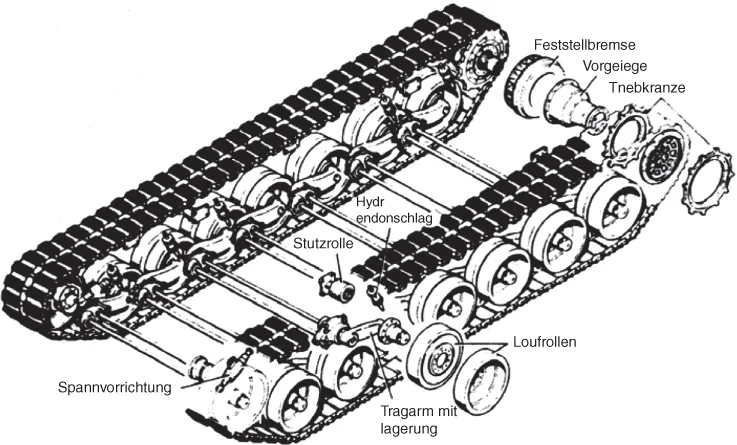
1.1 General Arrangement


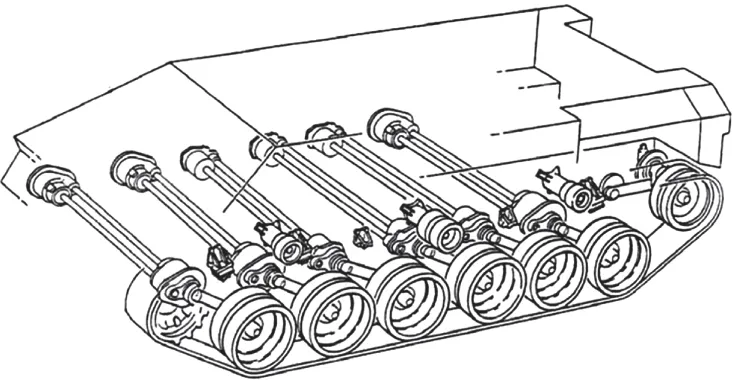
1.2 Transverse Torsion Bars

Table of contents
- Cover
- Table of Contents
- Dedication
- Series Preface
- Acknowledgements
- Introduction
- Chapter 1: Tracked Vehicle Running Gear and Suspension Systems
- Chapter 2: Vehicle Track Systems
- Chapter 3: Tracked Vehicle Suspension Performance: Modelling and Testing
- Chapter 4: Controllable Suspensions
- Chapter 5: Wheeled Vehicle Drivelines and Suspensions
- Chapter 6: Wheeled Vehicle Suspension Performance
- Chapter 7: Steering Performance of Tracked and Wheeled Vehicles
- Chapter 8: Soft‐Soil Performance of Wheeled and Tracked Vehicles
- Chapter 9: Effect of Free, Locked and Limited‐Slip Differentials on Traction and Steering Performance
- Chapter 10: Articulated Vehicles
- Chapter 11: Vehicle Rollover Behaviour
- Notation
- Abbreviations
- Bibliography
- Index
- End User License Agreement