A wide-ranging treatment of fundamental rotordynamics in order to serve engineers with the necessary knowledge to eliminate various vibration problems.
New to this edition are three chapters on highly significant topics:
Vibration Suppression - The chapter presents various methods and is a helpful guidance for professional engineers.
Magnetic Bearings - The chapter provides fundamental knowledge and enables the reader to realize simple magnetic bearings in the laboratory.
Some Practical Rotor Systems - The chapter explains various vibration characteristics of steam turbines and wind turbines.
The contents of other chapters on Balancing, Vibrations due to Mechanical Elements, and Cracked Rotors are added to and revised extensively.
The authors provide a classification of rotating shaft systems and general coverage of key ideas common to all branches of rotordynamics. They offers a unique analysis of dynamical problems, such as nonlinear rotordynamics, self-excited vibration, nonstationary vibration, and flow-induced oscillations. Nonlinear resonances are discussed in detail, as well as methods for shaft stability and various theoretical derivations and computational methods for analyzing rotors to determine and correct vibrations.
This edition also includes case studies and problems.
eBook - ePub
Linear and Nonlinear Rotordynamics
A Modern Treatment with Applications
- English
- ePUB (mobile friendly)
- Available on iOS & Android
eBook - ePub
About this book
Trusted by 375,005 students
Access to over 1.5 million titles for a fair monthly price.
Study more efficiently using our study tools.
Information
1
Introduction
1.1 Classification of Rotor Systems
In general, rotating machinery consists of disks of various shapes, shafts whose diameters change depending on their longitudinal position, and bearings situated at various positions.1 In vibration analyses, such a complex rotor system is simplified and a suitable mathematical model is adopted. In this modeling process, we must know which parameters are important for the system.
Rotating machines are classified according to their characteristics as follows: If the deformation of the rotating shaft is negligible in the operating speed range, it is called a rigid rotor. If the shaft deforms appreciably at some rotational speed in the operating speed range, it is called a flexible rotor. We cannot determine to which of these categories the rotor system belongs by considering only its dimensions. In rotordynamics, the rotating speeds that produce resonance responses due to mass eccentricity are called critical speeds. The deformation of a rotor becomes highest in the vicinity of the critical speed. Therefore, the range of the rated speed relative to these critical speeds determines whether the rotor is rigid or flexible.
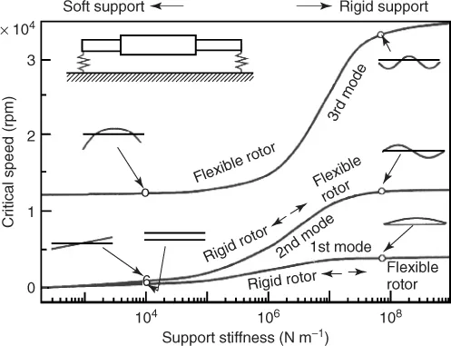
Figure 1.1 called a critical speed diagram shows variations of critical speeds and vibration modes versus the stiffness of the supports for a symmetrical rotor. The left part of this figure represents values for rotors that are supported softly. In the first and second modes, the rotors do not deform appreciably but the supporting parts deflect. In this case, the rotor is considered to be a rigid rotor. As the stiffness of the supports decreases, the natural frequency of these modes approaches zero. In the third mode, the rotor deforms and it is considered to be a flexible rotor. Depending on the type of mode to be discussed, the same system may be considered as a rigid or a flexible rotor. On the right part of this figure, deformation occurs in all three modes and therefore the rotor is considered to be flexible in every mode.
Figure 1.1 Critical speeds and mode shape versus the stiffness of the bearing support.
In some models, disks are considered to be rigid and the distributed mass of an elastic shaft is concentrated at the disk positions. Such a model is called a lumped-parameter system. If a flexible rotor with distributed mass and stiffness is considered, this model is called a distributed-parameter system or continuous rotor system. The mathematical treatment of the latter is more difficult than that of the former because it is governed by the partial differential equations.
Rotors are sometimes classified into vertical shaft systems and horizontal shaft systems. We mainly discuss the former model, however, the latter model tends to be considered in cases in which we must clarify the effect of gravity.
Rotors are sometimes classified as high-speed rotors or low-speed rotors. In this case, speed means the angular velocity or the peripheral velocity. Since high angular velocity often causes vibration, we use the term in association with the first definition in this book. The boundary between high and low is not clear and it differs depending on the situation. In some cases, the major critical speed is considered as the boundary. In ball bearing engineering, the term refers to the latter definition because it determines heating due to friction. The dimensionless parameter called DN value is used as an index related to the peripheral velocity. This value is defined as the product of the shaft diameter (mm) and the rotational speed (rpm). However, the unit symbol (mm · rpm) is omitted from the result of the calculation. Concerning high peripheral velocity, ball bearings and roller bearings of a main shaft of an aircraft engine have attained velocities of as much as DN = 3 × 10⁶ in a laboratory setting, though in practice these bearings are generally used at approximately 2.2 × 10⁶ (Zaretsky, 1998). With regard to high angular velocity bearings, the spindle of a drill for dental use operates at approximately 50 × 104rpm. However, since its shaft diameter is small, its DN value is consequently relatively small. For example, a bearing with an inner diameter of 3.175 mm used in dental drilling operates at approximately DN = 1.6 × 10⁶.
1.2 Historical Perspective
The evolution of research in the field of rotordynamics is shown in Figure 1.2. Research on rotordynamics spans at least a 140-year history, starting with Rankine's paper on whirling motions of a rotor in 1869. Rankine discussed the relationship between centrifugal and restoring forces and concluded that operation above a certain rotational speed is impossible. Although this conclusion was wrong, his paper (refer to the “Topic: The First Paper on Rotordynamics”) is important as the first publication on rotordynamics. The research progressed significantly at the end of the nineteenth century with contributions by de Laval and others. De Laval, an engineer in Sweden, invented a one-stage steam turbine and succeeded in its operation. He first used a rigid rotor, but later used a flexible rotor and showed that it was possible to operate above the critical speed by operating at a rotational speed about seven times the critical speed (Stodola, 1924).
Figure 1.2 History of rotordynamics.
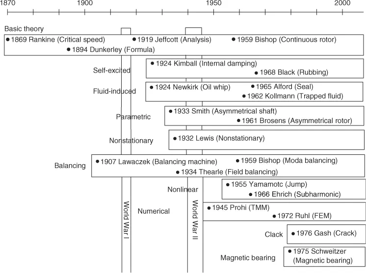
In the early days, the major concern for researchers and designers was to predict the critical speed, because the first thing that had to be done in designing rotating machinery was to avoid resonance. Dunkerley (1894) derived an empirical formula that gave the lowest critical speed for a multirotor system. He was the first to use the term “critical speed” for the resonance rotational speed. The word “critical,” which refers to a state or a value at which an abrupt change in a quality or state occurs, was coined possibly based on Rankine's conclusion mentioned above. Holzer (1921) proposed an approximate method to calculate the natural frequencies and mode shapes of torsional vibrations.
The first recorded fundamental theory of rotordynamics can be found in a paper written by Jeffcott (1919) . We can appreciate Jeffcott's great contributions if we recall that a shaft with a disk at the midspan is called the Jeffcott rotor, especially among researchers in the United States. This simplified fundamental rotor system is also called the Laval rotor, named after de Laval.
The developments made in rotordynamics up to the beginning of the twentieth century are detailed in the masterpiece written by Stodola (1924). This superb book explains nearly the entire field related to steam turbines. Among other things, this book includes the dynamics of elastic shafts with disks, the dynamics of continuous rotors without considering the gyroscopic moment, the balancing of rigid rotors, and methods for determining approximate values of critical speeds of rotors with variable cross sections.
Thereafter, the center of research shifted from Europe to the United States, and the scope of rotordynamics expanded to consider various other phenomena. Campbell (1924) at General Electric investigated vibrations of steam turbines in detail. His diagram, representing critical speed in relation to the cross points of natural frequency curves and the straight lines proportional to the rotational speed, is now widely used and referred to as the Campbell diagram. As the rotational speed increased above the first critical speed, the occurrence of self-excited vibrations became a serious problem. In the 1920s, Newkirk (1924) and Kimball (1924) first recognized that internal friction of shaft materials could cause an unstable whirling motion. These phenomena, in which friction that ordinarily dampens vibration causes self-excited vibration, attracted the attention of many researchers. Newkirk and Taylor (1925) investigated an unstable vibration called oil whip, which was due to an oil film in the journal bearings. Rotor is generally surrounded by a stator such as seals with a small clearance. Newkirk (1926) showed a forward whirl induced by a hot spot on the rotor surface, which was generated by the contact of the rotor and the surroundings. This hot spot instability is called the Newkirk effect.
About a decade later, the study of asymmetrical shaft systems and asymmetrical rotor systems began. The former are systems with a directional difference in shaft stiffness, and the latter are those with a directional difference in rotor inertia. Two pole generator rotors and propeller rotors are examples of such systems. As these directional differences rotate with the shaft, terms with time-varying coefficients appear in the governing equations. These systems therefore fall into the category of parametrically excited systems. The most characteristic property of asymmetrical systems is the appearance of unstable vibrations in some rotational speed ranges. Smith (1933)'s report is a pioneering work on this topic. Various phenomena related to the asymmetries of rotors were investigated actively in the middle of the twentieth century by Taylor (1940) and Foote, Poritsky, and Slade (1943), Brosens and Crandall (1961), and Yamamoto and Ota (1963a, 1963b, 1964).
Nonstationary phenomena during passage through critical speeds have been studied since Lewis reported his investigation on the Jeffcott rotor in 1932. Numerous reports on this topic are classified into two groups. One group classifies nonstationary phenomena that occur in a process with a constant acceleration and the other classifies phenomena that occur with a limited driving torque. In the latter case, mutual interaction between the driving torque and the shaft vibration must be considered. As the theoretical analysis of such transition problems is far more difficult than that of stationary oscillations, many researchers adopted numerical integrations. The asymptotic method developed by the Russian school of Krylov and Bogoliubov (1947) and Bogoliubov and Mitropol'skii (1958) considerably boosted the research on this subject.
The vibrations of rotors with continuously distributed mass were also studied. The simplest continuous rotor model corresponding to the Euler beam was first studied in the book by Stodola (1924). In ...
Table of contents
- Cover
- Related Titles
- Title Page
- Copyright
- Dedication
- Foreword to the First Edition
- Preface to the First Edition
- Preface to the Second Edition
- Acknowledgments
- Chapter 1: Introduction
- Chapter 2: Vibrations of Massless Shafts with Rigid Disks
- Chapter 3: Vibrations of a Continuous Rotor
- Chapter 4: Balancing
- Chapter 5: Vibrations of an Asymmetrical Shaft and an Asymmetrical Rotor
- Chapter 6: Nonlinear Vibrations
- Chapter 7: Self-Excited Vibrations Due to Internal Damping
- Chapter 8: Nonstationary Vibrations during Passage through Critical Speeds
- Chapter 9: Vibrations due to Mechanical Elements
- Chapter 10: Flow-Induced Vibrations
- Chapter 11: Vibration Suppression
- Chapter 12: Some Practical Rotor Systems
- Chapter 13: Cracked Rotors
- Chapter 14: Finite Element Method
- Chapter 15: Transfer Matrix Method
- Chapter 16: Measurement and Signal Processing
- Chapter 17: Active Magnetic Bearing
- Appendix A: Moment of Inertia and Equations of Motion
- Appendix B: Stability above the Major Critical Speed
- Appendix C: Derivation of Equations of Motion of a 4 DOF Rotor System by Using Euler Angles
- Appendix D: Asymmetrical Shaft and Asymmetrical Rotor with Four Degrees of Freedom
- D.1 4 DOF Asymmetrical Shaft System
- D.2 4 DOF Asymmetrical Rotor System
- Reference
- Appendix E: Transformation of Equations of Motion to Normal Coordinates: 4 DOF Rotor System
- E.1 Transformation of Equations of Motion to Normal Coordinates
- E.2 Nonlinear Terms
- References
- Appendix F: Routh–Hurwitz Criteria for Complex Expressions
- References
- Appendix G: FFT Program
- References
- Index
Frequently asked questions
Yes, you can cancel anytime from the Subscription tab in your account settings on the Perlego website. Your subscription will stay active until the end of your current billing period. Learn how to cancel your subscription
No, books cannot be downloaded as external files, such as PDFs, for use outside of Perlego. However, you can download books within the Perlego app for offline reading on mobile or tablet. Learn how to download books offline
Perlego offers two plans: Essential and Complete
- Essential is ideal for learners and professionals who enjoy exploring a wide range of subjects. Access the Essential Library with 800,000+ trusted titles and best-sellers across business, personal growth, and the humanities. Includes unlimited reading time and Standard Read Aloud voice.
- Complete: Perfect for advanced learners and researchers needing full, unrestricted access. Unlock 1.5M+ books across hundreds of subjects, including academic and specialized titles. The Complete Plan also includes advanced features like Premium Read Aloud and Research Assistant.
We are an online textbook subscription service, where you can get access to an entire online library for less than the price of a single book per month. With over 1.5 million books across 990+ topics, we’ve got you covered! Learn about our mission
Look out for the read-aloud symbol on your next book to see if you can listen to it. The read-aloud tool reads text aloud for you, highlighting the text as it is being read. You can pause it, speed it up and slow it down. Learn more about Read Aloud
Yes! You can use the Perlego app on both iOS and Android devices to read anytime, anywhere — even offline. Perfect for commutes or when you’re on the go.
Please note we cannot support devices running on iOS 13 and Android 7 or earlier. Learn more about using the app
Please note we cannot support devices running on iOS 13 and Android 7 or earlier. Learn more about using the app
Yes, you can access Linear and Nonlinear Rotordynamics by Yukio Ishida,Toshio Yamamoto in PDF and/or ePUB format, as well as other popular books in Technology & Engineering & Power Resources. We have over 1.5 million books available in our catalogue for you to explore.