Electrical Insulation for Rotating Machines
eBook - ePub

Electrical Insulation for Rotating Machines

Design, Evaluation, Aging, Testing, and Repair

Greg C. Stone, Ian Culbert, Edward A. Boulter, Hussein Dhirani

Share book
  1. English
  2. ePUB (mobile friendly)
  3. Available on iOS & Android
eBook - ePub

Electrical Insulation for Rotating Machines

Design, Evaluation, Aging, Testing, and Repair

Greg C. Stone, Ian Culbert, Edward A. Boulter, Hussein Dhirani

Book details
Book preview
Table of contents
Citations

About This Book

A fully expanded new edition documenting the significant improvements that have been made to the tests and monitors of electrical insulation systems

Electrical Insulation for Rotating Machines: Design, Evaluation, Aging, Testing, and Repair, Second Edition covers all aspects in the design, deterioration, testing, and repair of the electrical insulation used in motors and generators of all ratings greater than fractional horsepower size. It discusses both rotor and stator windings; gives a historical overview of machine insulation design; and describes the materials and manufacturing methods of the rotor and stator winding insulation systems in current use (while covering systems made over fifty years ago). It covers how to select the insulation systems for use in new machines, and explains over thirty different rotor and stator winding failure processes, including the methods to repair, or least slow down, each process. Finally, it reviews the theoretical basis, practical application, and interpretation of forty different tests and monitors that are used to assess winding insulation condition, thereby helping machine users avoid unnecessary machine failures and reduce maintenance costs.

Electrical Insulation for Rotating Machines:

  • Documents the large array of machine electrical failure mechanisms, repair methods, and test techniques that are currently available
  • Educates owners of machines as well as repair shops on the different failure processes and shows them how to fix or otherwise ameliorate them
  • Offers chapters on testing, monitoring, and maintenance strategies that assist in educating machine users and repair shops on the tests needed for specific situations and how to minimize motor and generator maintenance costs
  • Captures the state of both the present and past "art" in rotating machine insulation system design and manufacture, which helps designers learn from the knowledge acquired by previous generations

An ideal read for researchers, developers, and manufacturers of electrical insulating materials for machines, Electrical Insulation for Rotating Machines will also benefit designers of motors and generators who must select and apply electrical insulation in machines.

Frequently asked questions

How do I cancel my subscription?
Simply head over to the account section in settings and click on “Cancel Subscription” - it’s as simple as that. After you cancel, your membership will stay active for the remainder of the time you’ve paid for. Learn more here.
Can/how do I download books?
At the moment all of our mobile-responsive ePub books are available to download via the app. Most of our PDFs are also available to download and we're working on making the final remaining ones downloadable now. Learn more here.
What is the difference between the pricing plans?
Both plans give you full access to the library and all of Perlego’s features. The only differences are the price and subscription period: With the annual plan you’ll save around 30% compared to 12 months on the monthly plan.
What is Perlego?
We are an online textbook subscription service, where you can get access to an entire online library for less than the price of a single book per month. With over 1 million books across 1000+ topics, we’ve got you covered! Learn more here.
Do you support text-to-speech?
Look out for the read-aloud symbol on your next book to see if you can listen to it. The read-aloud tool reads text aloud for you, highlighting the text as it is being read. You can pause it, speed it up and slow it down. Learn more here.
Is Electrical Insulation for Rotating Machines an online PDF/ePUB?
Yes, you can access Electrical Insulation for Rotating Machines by Greg C. Stone, Ian Culbert, Edward A. Boulter, Hussein Dhirani in PDF and/or ePUB format, as well as other popular books in Technology & Engineering & Electrical Engineering & Telecommunications. We have over one million books available in our catalogue for you to explore.

Chapter 1

Rotating Machine Insulation Systems

Since electrical motors and generators were invented, a vast range of electrical machine types have been created. In many cases, different companies called the same type of machine or the same component by completely different names. Therefore, to avoid confusion, before a detailed description of motor and generator insulation systems can be given, it is prudent to identify and describe the types of electrical machines that are discussed in this book. The main components in a machine, as well as the winding subcomponents, are identified and their purposes described.
Although this book concentrates on machines rated at 1 kW or more, much of the information on insulation system design, failure, and testing can be applied to smaller machines, linear motors, servomotors, etc. However, these latter machine types will not be discussed explicitly.

1.1 Types of Rotating Machines

Electrical machines rated at about 1 HP or 1 kW and above are classified into two broad categories: (i) motors, which convert electrical energy into mechanical energy (usually rotating torque) and (ii) generators (also called alternators), which convert mechanical energy into electrical energy. In addition, there is another machine called a synchronous condenser that is a specialized generator/motor generating reactive power. Consult any general book on electrical machines for a more extensive description of machines and how they work [1, 2]. An excellent book that focuses on all aspects of turbogenerators has been written by Klempner and Kerszenbaum [3].
Motors or generators can be either AC or DC, that is, they can use/produce alternating current or direct current. In a motor, the DC machine has the advantage that its output rotational speed can be easily changed. Thus, DC motors and generators were widely used in industry in the past. However, with variable-speed motors now easily made by combining an AC motor with an electronic “inverter-fed drive” (IFD), DC motors in the hundreds of kilowatt range and above are becoming less common.
Machines are also classified according to the type of cooling used. They can be directly or indirectly cooled, using air, hydrogen, and/or water as a cooling medium.
This book concentrates on AC induction and synchronous motors, as well as synchronous and induction generators. Other types of machines exist; however, these motors and generators constitute the vast majority of electrical machines rated more than 1 kW presently used around the world.

1.1.1 AC Motors

Nearly all AC motors have a single-phase (for motors less than about 1 kW) or three-phase stator winding through which the input current flows. For AC motors, the stator is also called the armature. AC motors are usually classified according to the type of rotor winding. The rotor winding is also known as a field winding in synchronous machines. A discussion of each type of AC motor follows.

Squirrel Cage Induction (SCI) Motor

The SCI motor (Figure 1.1) is by far the most common type of motor made, with millions manufactured each year. The rotor produces a magnetic field by transformer-like AC induction from the stator (armature) winding. The squirrel cage induction motor (Figure 1.1) can range in size from a fraction of a horsepower (<1 kW) to many tens of thousands of horsepower (>60 MW). The predominance of the SCI motor is attributed to the simplicity and ruggedness of the rotor. SCI rotors normally do not use any electrical insulation. In an SCI motor, the speed of the rotor is usually 1% or so slower than the “synchronous” speed of the rotating magnetic field in the air gap created by the stator winding. Thus, the rotor speed “slips” behind the speed of the air gap magnetic flux [1, 2]. The SCI motor is used for almost every conceivable application, including fluid pumping, fans, conveyor systems, grinding, mixing, gas compression, and power tool operation.
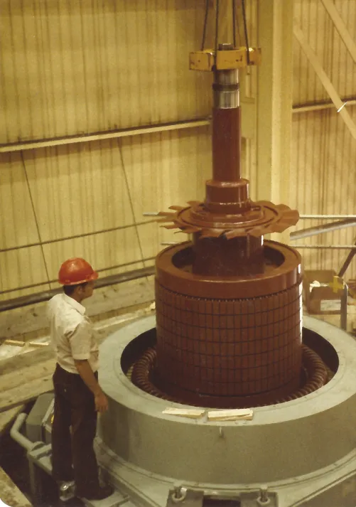
c01f001
Figure 1.1 Photograph of an SCI rotor being lowered into the squirrel cage induction motor stator.

Wound Rotor Induction Motor

The rotor is wound with insulated wire and the leads are brought off the rotor via slip rings. In operation, a current is induced into the rotor from the stator, just as for an SCI motor. However, in the wound rotor machine, it is possible to limit the current in the rotor winding by means of an external resistance or slip-energy recovery system. This permits some control of the rotor speed. Wound rotor induction motors are relatively rare because of the extra maintenance required for the slip rings. IFDs with SCI motors now tend to be preferred for variable-speed applications as they are often a more reliable, cheaper alternative.

Synchronous Motor

This motor has a direct current flowing through the rotor (field) winding. The current creates a DC magnetic field, which interacts with the rotating magnetic field from the stator, causing the rotor to spin. The speed of the rotor is exactly related to the frequency of the AC current supplied to the stator winding (50 or 60 Hz). There is no “slip.” The speed of the rotor depends on the number of rotor pole pairs (a pole pair contains one north pole and one south pole) times the AC frequency. There are two main ways of obtaining a DC current in the rotor. The oldest method, is to feed current onto the rotor by means of two slip rings (one positive, one negative). Alternatively, the “brushless exciter” method, by most manufacturers, uses a DC winding mounted on the stator to induce a current in an auxiliary three-phase winding mounted on the rotor to generate AC current, which is rectified (by “rotating” diodes) to DC. Synchronous motors require a small “pony” motor to run the rotor up to near synchronous speed. Alternatively, an SCI type of winding on the rotor can be used to drive the motor up to speed, before DC current is permitted to flow in the main rotor winding. This winding is referred to as an amortisseur or damper winding. Because of the more complicated rotor and additional components, synchronous motors tend to be restricted to very large motors today (>10 MW) or very slow speed motors. The advantage of a synchronous motor is that it usually requires less “inrush” current on startup in comparison to an SCI motor, and the speed is more constant. In addition, the operating energy costs are lower as, by adjusting the rotor DC current, one can improve the power factor of the motor, reducing the need for reactive power and the associated AC supply current. Refer to Section 1.1.2 for further subdivision of the types of synchronous motor rotors. Two-pole synchronous motors use round rotors, as described in Section 1.1.2.

1.1.2 Synchronous Generators

Although induction generators do exist (Section 1.1.3), particularly in wind turbine generators, they are relatively rare compared to synchronous generators. Virtually all generators used by electrical utilities are of the synchronous type. In synchronous generators, DC current flows through the rotor (field) winding, which creates a magnetic field from the rotor. At the same time, the rotor is spun by a steam turbine (using fossil or nuclear fuel), gas turbine, diesel engine, or hydroelectric turbine. The spinning DC field from the rotor induces current to flow in the stator (armature) winding. As for motors, the following types of synchronous generators are determined by the design of the rotor, which is primarily a function of the speed of the driving turbine.

Round Rotor Generators

Also known as cylindrical rotor machines, round rotors (Figure 1.2) are most common in high speed machines, that is, machines in which the rotor revolves at about 1000 rpm or more. Where the electrical system operates at 60 Hz, the rotor speed is usually either 1800 or 3600 rpm. The relatively smooth surface of the rotor reduces “windage” losses, that is, the energy lost to moving the air (or other gas) around in the air gap between the rotor and the stator—the fan effect. This loss can be ...

Table of contents