![]()
Chapter 1
Introduction to Circularly Polarized Antennas
1.1 Introduction
Circularly polarized (CP) antennas are a type of antenna with circular polarization. Due to the features of circular polarization, CP antennas have several important advantages compared to antennas using linear polarizations, and are becoming a key technology for various wireless systems including satellite communications, mobile communications, global navigation satellite systems (GNSS), wireless sensors, radio frequency identification (RFID), wireless power transmission, wireless local area networks (WLAN), wireless personal area networks (WPAN), Worldwide Interoperability for Microwave Access (WiMAX) and Direct Broadcasting Service (DBS) television reception systems. Lots of progress in research and development has been made during recent years.
The CP antenna is very effective in combating multi-path interferences or fading [1, 2]. The reflected radio signal from the ground or other objects will result in a reversal of polarization, that is, right-hand circular polarization (RHCP) reflections show left-hand circular polarization (LHCP). A RHCP antenna will have a rejection of a reflected signal which is LHCP, thus reducing the multi-path interferences from the reflected signals.
The second advantage is that CP antenna is able to reduce the ‘Faraday rotation’ effect due to the ionosphere [3, 4]. The Faraday rotation effect causes a significant signal loss (about 3 dB or more) if linearly polarized signals are employed. The CP antenna is immune to this problem, thus the CP antenna is widely used for space telemetry applications of satellites, space probes and ballistic missiles to transmit or receive signals that have undergone Faraday rotation by travelling through the ionosphere.
Another advantage of using CP antennas is that no strict orientation between transmitting and receiving antennas is required. This is different from linearly polarized antennas which are subject to polarization mismatch losses if arbitrary polarization misalignment occurs between transmitting and receiving antennas. This is useful for mobile satellite communications where it is difficult to maintain a constant antenna orientation. With CP, the strength of the received signals is fairly constant regardless of the antenna orientation. These advantages make CP antennas very attractive for many wireless systems.
This chapter serves as a basis for the chapters that follow. It will introduce some basic parameters of antennas. Different types of basic CP antennas such as CP microstrip patch antenna, helix, quadrifilar helix antenna (QHA), printed quadrifilar helix antenna (PQHA), spiral antenna, CP dielectric resonator antenna (DRA), CP slot antennas, CP horns and CP arrays will be described and basic designs illustrated. Typical requirements and challenges in CP antenna designs will be discussed at the end.
1.2 Antenna Parameters
An antenna is a device which can receive or/and transmit radio signals. As a receiving device, it can collect the radio signals from free space and convert them from electromagnetic waves (in the free space) into guided waves in transmission lines; as a transmitting device, it can transmit radio signals to free space by converting the guided waves in transmission lines into the electromagnetic waves in the free space. In some cases, an antenna can serve both functions of receive and transmit.
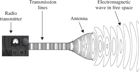
Figure 1.1 depicts the basic operation of a transmit antenna. As shown, the information (voice, image or data) is processed in a radio transmitter and then the output signal from the transmitter propagates along the transmission lines before finally being radiated by the antenna. The antenna converts the guided-wave signals in the transmission lines into electromagnetic waves in the free space. The operation of a receive antenna follows a reverse process, that is, collecting the radio signals by converting the electromagnetic waves in free space into guided-wave signals in the transmission lines, which are then fed into radio receivers.
1.2.1 Input Impedance
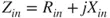
The input impedance Zin is defined as the impedance presented by an antenna at its feed point, or the ratio of the voltage to current at the feed point [5]. The input impedance is usually a complex number which is also frequency dependent. It can be expressed as
The real part of the impedance, Rin, includes the radiation resistance Rr of the antenna and the loss resistance RL. Rr relates to the power radiated by the antenna, and RL relates to the power dissipated in the antenna due to losses in dielectric materials, antenna conductor losses, and so on.
1.2.2 Reflection Coefficient, Return Loss and Voltage Standing Wave Ratio
The antenna input impedance needs to be matched with the characteristic impedance of the transmission line connected to the feed point of the antenna. Usually a 50 Ω cable is used to feed the antenna. Thus the antenna input impedance needs to be equal to 50 Ω, otherwise there will be an impedance mismatch at the antenna feed point. In the case of impedance mismatch, there will be signal reflections, that is, some of signals fed to the antenna will be reflected back to the signal sources.
The reflection coefficient Γ denotes the ratio of the reflected wave voltage to the incident wave voltage [5]. The reflection coefficient at the feed point of the antenna can be related to the antenna input impedance by the following equation:
Here, Zin and Zo denote the input impedance of the antenna, and the characteristic impedance of the transmission line connected to the antenna feed point, respectively. As shown in equation (1.2), the reflection coefficient is zero if Zin is equal to Zo.
Return loss (in dB) is defined as:
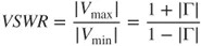
For a well-designed antenna, the required return loss should usually be at least 10 dB, though some antennas on small mobile terminals can only achieve about 6 dB. Voltage Standing Wave Ratio (VSWR) is the ratio of the maximum voltage Vmax to the minimum voltage Vmin on the transmission line. It is defined as:
1.2.3 Radiation Patterns
The radiation pattern of the antenna illustrates the distribution of radiated power in the space [6–9]. It can be plotted in a spherical coordinate system as the radiated power versus the elevation angle (
θ) or the azimuth angle (
).
Figure 1.2 shows a radiation pattern plotted as the radiated power versus the elevation angle (
θ). As shown, the radiation pattern has a few lobes. The main lobe is the lobe containing the majority of radiated power. The lobe radiating towards the backward direction is the back lobe. Usually there will also be a few other small lobes called the side lobes. The 3-dB beamwidth indicated in the figure refers to the angular range between two points where the radiated power is half the maximum radiated...