![]()
Chapter 1
Non-imaging Focusing Heliostat
Kok-Keong Chong
Faculty of Engineering and Science, Universiti Tunku Abdul Rahman, Kuala Lumpur, Malaysia
Abstract
Overcoming astigmatism has always been a great challenge in designing a heliostat capable of focusing the sunlight on a small receiver throughout the year. In this chapter, a non-imaging focusing heliostat with dynamic adjustment of facet mirrors in a group manner is presented for optimizing the astigmatic correction in a wide range of incident angles. Non-imaging focusing heliostat that consists of m × n facet mirrors can carry out continuous astigmatic correction during sun-tracking with the use of only (m + n − 2) controllers. A further simplified astigmatic correction of non-imaging focusing heliostat is also discussed which reduces the number of controllers from (m + n − 2) to only two. A detailed optical analysis is carried out and the simulated result has shown that the two-controller system can perform comparably well in astigmatic correction with a much simpler and more cost effective design. The new heliostat is not only designed to serve the purpose of concentrating sunlight to several hundreds of suns, but also to significantly reduce the variation of solar flux distribution with incident angle.
Keywords: Non-imaging focusing heliostat, new heliostat, optical analysis, solar flux
1.1 Introduction
There are two fundamental designs of solar concentrator technologies for harnessing high concentration solar energy: on-axis and off-axis focusing techniques. The most popular devices for on-axis focusing include parabolic dish, parabolic trough, spherical bowl (or so-called Fixed Mirror Distributed Focus), Fresnel lens, etc. [1, 2]. The off-axis focusing device involves the use of heliostat to focus sunlight onto a fixed receiver in the systems such as the central power tower, the solar furnace, etc. [2–7]. The on-axis focusing devices are usually used for distributed and smaller scale power generation (in the range from several kW to tens of kW) compared to that of off-axis focusing devices in the application of a central receiver system. For the central power tower, the concave mirrors used for the heliostat encounter a serious deterioration in focused image due to the off-axis aberration.
Off-axis aberration or astigmatism is a key factor in limiting the solar concentration ratio, especially for the central tower system that consists of a stationary receiver located in a field of focusing heliostats [8]. Full correction of the astigmatism requires a continuous adjustment in the local curvature of the reflector in both space and time. Although this method has been implemented in extremely large telescopes, it is obviously impractical for solar energy application because it would impose a very expensive and complicated control system with a total of 2 × m × n motors to orient each facet to its own unique direction for the heliostat composed of m × n facets. As a result, a new non-imaging focusing heliostat, that employs a clever approach to maneuver the facets in group manner for astigmatic correction has been proposed. Many research works on non-imaging focusing heliostat have been carried out by Chen et al. [9–15], Chong et al. [16–22] and Lim et al. [23] to establish the principle and technology of the new heliostat. Overall, there are two major advancements achieved in the new heliostat compared to the conventional heliostat that has remained unchanged for many decades [24]. One is the first mathematical derivation of the new spinning-elevation tracking formula to replace the commonly used azimuth-elevation tracking. Even the principle of spinning-elevation or target-aligned tracking method was first discussed by Ries et al. [25] and Zaibel et al. [26], but they did not propose any method of implementation in their papers such as derivation of new sun-tracking formula or construction of a prototype to implement the new tracking method. The second advancement is the correction of the first order astigmatism with the innovative line movements of the facets instead of trivial individual movements that would lead to complex and expensive mechanics.
1.2 The Principle of Non-imaging Focusing Heliostat (NIFH)
In the design of the non-imaging focusing heliostat (NIFH), mirrors are arranged into rows and columns. The central column is maintained in the optical plane by rotating the frame. The master mirror is fixed at the center with slave mirrors surrounding it, they share the same frame but the slave mirrors have two extra moving freedoms about their pivot points. To focus all the mirror images into one fixed target, each slave mirror is angularly moved about its pivot point to reflect sunrays onto the same target as the master mirror. The result at the target is the superposition of individual mirror images. As the sunlight is not coherent, the result is the algebra sum of the energy of the beams without a specific optical image.
1.2.1 Primary Tracking (Global Movement for Heliostat Frame)
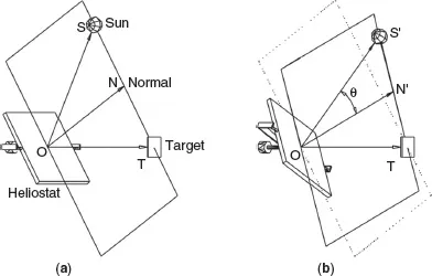
The purpose of primary tracking is to target the solar image of the master mirror into a stationary receiver. Then, this image acts as a reference for secondary tracking where all the slave mirror images will be projected on it. In
Figure 1.1(a), we define
as the vector normal to the reflector surface;
as the vector that points to the sun;
as the vector that points to a fixed target.
Figure 1.1(b) shows the rotation of the plane of reflection, that plane which contains the three vectors (
,
and
), during primary tracking. In
Figure 1.1(b), the vector
points to the new position of the sun and the vector
’ is the reflector normal of the new orientation so that the sunlight is still reflected towards the target. The tracking movement can be studied by two independent components (
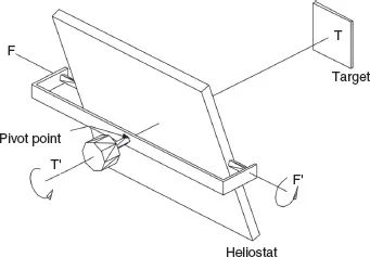
Figure 1.2):
a. Spinning movement:
The heliostat has to rotate about the TT’ axis so that the plane of reflection can follow the rotation of the vector
. Therefore, as the sun moves through the sky from the morning to solar noon, the plane will rotate starting from horizontal and turning to vertical. The angular movement about this spinning axis is denoted as θ.
b. Elevation movement:
The rotation of the heliostat about the FF’ axis (perpendicular to the plane) will adjust the reflector normal position within the plane until it bisects the angle between
and
. As a result, the sunlight will be reflected onto the target. This angular movement depends on the incidence angle of the sun relative to the heliostat surface normal and it is denoted as θ.
The formulas for ρ and θ can be derived by transformation study of two different coordinate systems: one attached to the center of the earth and the other attached to the local heliostat.
In
Figure 1.3(a), by defining a coordinate system with the origin, C, set at the center of the earth, the CM axis is a line from the origin to the intersection point between the equator and the meridian of the observer at Q. The CE (east) axis in the equatorial plane is perpendicular to the CM axis. The third orthogonal axis, CP, is the rotation axis of the earth. Vector
pointing to the sun can be described in terms of its direction cosines,
Sm,
Se and
Sp to ...